Page 14
Copyright © 2012 Kato Engineering, Inc. All rights reserved
Install the portion of the coupling that fi ts into the engine fl ywheel
following the manufacturer’s recommended procedures and in accor-
dance with engine manufacturer’s specifi cations. Check the coupling’s
radial and face runout by mounting a dial indicator to the engine
fl ywheel housing as shown in Figure 9. The maximum radial and face
runout on the coupling must not exceed 0.004 inch. Measure and record
the engine crank shaft endplay Set the engine endplay at a position of
one half of the measured distance.
Measure the generator endplay. Compare the measured endplay to the
factory recorded endplay located on the Generator Warranty/Test Tag.
Once this is verifi ed, thrust the generator shaft all the way to the engine,
then back off that location .020”, or .508mm. This will allow for the
thermal growth of the shaft.
If the generator has “fl oating bearings”, align the face of the outer seat
with the groove in the shaft (electrical center).
Two-bearing alignment
Follow the tolerances specifi ed by the coupling manufacturer when they
are less than described in this manual.
Use shims, if necessary, between the mounting pad and the base to
properly level and align the generator to the prime mover.
Install the coupling(s) on the generator and engine drive shafts in
accordance with coupling manufacturer installation procedures. Check
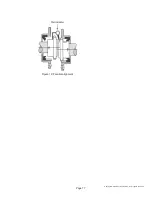
the generator coupling’s radial and face runout by mounting a dial
indicator to the generator adapter as shown in Figure 8. The maximum
radial and face runout on the coupling must not exceed 0.003 inch.
Figure 8: Generator coupling check
Shaft
Adapter
Dial indicator
pointer for radial
runout
Dial indicator
pointer for face
runout


