Page 27
Copyright © 2012 Kato Engineering, Inc. All rights reserved
NOTICE: Operating the unit beyond name-
plate values may cause equipment damage
or failure.
Continuous operation
Operate the generator within the nameplate values . If the generator is
operated below the rated power factor and voltage, decrease the kVA to
prevent overheating of the fi eld and stator windings. Consult the factory
for derating factors if the application requires the unit to be operated
beyond nameplate values.
Rotor overheating may occur when the generator is carrying excessive
unbalanced loads. Negative sequence currents fl owing in the fi eld pole
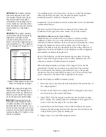
face cause the rotor heating. For a general guide to the allowable phase
unbalance, see Figure 20, Guide to allowable phase unbalance (which is
based on a 10% equivalent negative sequence current).
The guide is used in the following manner: Find the point where the
vertical line (determined by the maximum current in any of the phases
and expressed in percent of rated current) crosses the horizontal line
(determined by the minimum current in any of the phases and expressed
in percent of rated current). Ensure the point where these two lines
intersect is within the permissible allowable unbalance region for safe
operation of the generator.
Loss of fi eld excitation can result in the unit operating out of
synchronization with the system when operating is parallel. This has the
effect of producing high currents in the rotor, which will cause damage
very quickly. Protective relays should be considered to open the circuit
breaker.
Idling
Unless the voltage regulator has V/Hz protection built in, having the
generator set in operating mode while idling the engine can cause
permanent equipment damage. If engine adjustments require that
the engine be run at idle speed and the regulator does not have V/Hz
protection, make the generator regulating system inoperative during
idling by one of the following methods:
When the generator is provided with a voltage shutdown switch, be sure
the switch is set to the idle position while the engine is running at idle
speed.
Where the generator set is provided with fi eld circuit breakers, set the
circuit breaker to the off position while the generator is running at idle
speed.
Where the generator set is provided with an automatic/manual control
switch that has an off position, switch it to off while the engine is
running at idle speed.
Where the generator set does not have any of the above options, remove
the wires from the voltage regulator input power terminals when the
engine is running at less than rated speed.


