Page 12
Copyright © 2012 Kato Engineering, Inc. All rights reserved
Install the portion of the coupling that fi ts into the engine fl ywheel
following the manufacturer’s recommended procedures and in accor-
dance with engine manufacturer’s specifi cations. Check the coupling’s
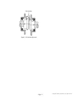
radial and face runout by mounting a dial indicator to the engine
fl ywheel housing as shown in Figure 6. The maximum radial and face
runout on the coupling must not exceed 0.004 inch.
Measure and record the engine crank shaft endplay Set the engine
endplay at a position of one half of the measured distance.
Measure the generator endplay. Compare the measured endplay to the
factory recorded endplay located on the Generator Warranty/Test Tag.
Once this is verifi ed, thrust the generator shaft all the way to the engine,
then back off that location .020”, or .508mm. This will allow for the
thermal growth of the shaft.
Mount the generator on the skid, and move the generator to within 0.010
inch of the engine. Place two 0.010-inch shims in the horizontal
(9 o’clock and 3 o’clock) positions between the generator adapter
and the engine fl ywheel housing. Raising the rear, exciter end of the
generator as necessary, place two 0.010-inch shims in the vertical (6
o’clock and 12 o’clock) positions between the generator adapter and
the engine fl ywheel housing. This will give a good starting point for
alignment. Remove the vertical shims at this time. (If necessary, mark
holes to be drilled on the base, and remove the generator at this time.)
Mount a dial indicator on the generator shaft or half coupling to the
fl ywheel radial surface for parallel alignment as shown in Figure 7.
IMPORTANT: The maximum allowable
fl ywheel runout is .0005” per inch of radius
with a maximum of .010”.
Shaft
Flywheel
Flywheel housing
Dial indicator pointer
for radial runout
Dial indicator
pointer for face
runout
Figure 6: Engine coupling check


