Page 16
Copyright © 2012 Kato Engineering, Inc. All rights reserved
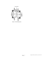
Angular alignment: Fasten a dial indicator to one of the coupling halves,
and scribe the position of the dial button on the face of the opposite
coupling half as shown in Figure 11. Rotate both shafts simultaneously,
keeping the fi nger or button on the indicator at the reference mark on the
coupling hub. Notice the reading on the indicator dial at each one quarter
revolution.
A variation of readings at different positions will indicate how the
machine needs to be adjusted to obtain a maximum misalignment of
0.005 inch for each inch of the coupling hub’s radius, total indicator
runout. Place or remove slotted shims from under the front or rear engine
or generator mounting pads and/or shift the front or back half of one
component from side to side until the components are properly aligned.
Tighten the mounting bolts, and recheck alignment.
Parallel alignment: Fasten a dial indicator to one of the coupling halves,
and scribe the position of the dial button on the top of the opposite
coupling half as shown in Figure 12. Rotate both shafts simultaneously,
keeping the fi nger or button on the indicator at the reference mark on the
coupling hub. Notice the reading on the indicator dial at each one quarter
revolution. A variation of readings at different positions will indicate how
the machine needs to be adjusted to obtain a maximum misalignment of
0.005 TIR. Compensation for engine thermal growth must be taken into
account on this measurement. Place or remove slotted shims from under
all of the engine or generator mounting pads and/or shift one component
from side to side until the components are properly aligned. Tighten the
mounting bolts, and recheck alignment.
Dial indicator
Figure 11: Angular alignment


