background image


Using Memory Functions

70 of 100

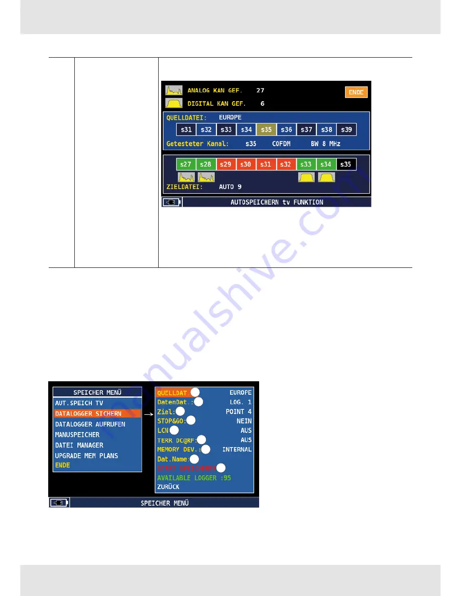
START SAVE

Activates the automatic search function and starts the chan-
nel search:

Depending on the meter operation mode, the display may 
vary.
If the meter displays 

START OVERWRITE

 instead of 

START 

SAVE

, it means that the destination file already exists and will 

be overwritten after the function has started.

19.3 

Datalogger Functions

19.3.1 

Save Datalogger

This function can be used additionally to a plan with the auto-memory or a standard chan-
nel plan to execute precise measurements of signal strength and quality for each channel 
listed in the selected channel plan. When the auto-memory is executed in a certain area to 
detect all receivable channels, the datalogger is typically used to describe the channels in 
terms of power level and main RF characteristics. The configuration menu:

1

2

3

4

5

6

7

8

9

Содержание MSK 130

Страница 1: ...Instructions for Use MSK 130 English You will find an English version of this document at www kathrein com IMPORTANT Read carefully before use ...

Страница 2: ... of Delivery 11 9 1 Optional Accessories 11 10 Abbreviations and Technical Terms 12 11 Device Description 14 11 1 Front Panel 14 11 2 Plan View 16 11 3 Right and Left Panels 17 12 Operating the Signal Meter 18 12 1 Turning the Device on and off 18 12 2 Locking the Keyboard and Touch Screen 18 12 3 Resetting the Device 18 12 4 Updating Firmware and Channel Plans 18 12 5 Resetting the Device to Fact...

Страница 3: ...CATV Configuration 35 14 5 Displaying Meter Info 36 14 6 SAT TV Threshold 36 14 7 IPTV Configuration only MSK 130 IA and MSK 130 OIA 37 14 8 Common Interface 39 14 9 Diagnostic 39 15 Main Menu 40 16 Measuring SAT TV CATV and Optical Signals 41 16 1 General Information 41 16 1 1 Selecting Signal Type 41 16 1 2 Activating and Deactivating Full Screen Mode 41 16 1 3 Selecting the Sound Mode 41 16 2 P...

Страница 4: ... 2 Automemory Only TV and CATV 69 19 3 Datalogger Functions 70 19 3 1 Save Datalogger 70 1 1 1 Recalling Data Logger 73 1 1 2 Manual Memory 73 1 1 3 File Manager 75 19 3 2 Copying Memory Plans 76 20 Special Functions 76 20 1 SAT Special Functions 76 20 1 1 SAT SCR 77 20 1 2 DUAL LNB 77 20 1 3 DiSEqC Motor 78 20 1 4 SAT Finder 79 20 1 5 Buzzer and Noise Margin 79 20 1 6 Attenuation Test 80 20 1 7 S...

Страница 5: ... 88 21 7 Performing Spectrum Analysis 88 21 8 Performing ASI Analysis 89 21 8 1 Performing HF and ASI Analysis 89 21 8 2 Performing IPTV Analysis 90 21 9 Activating Data Logger 92 21 9 1 Activating Data Logger 92 21 10 Using Memory Functions 93 21 10 1 Recalling a Memory Plan from the Meter 93 21 10 2 Recalling Data Logger 93 22 Technical Data 94 23 Service 96 24 Cleaning 97 25 Disposal 98 ...

Страница 6: ...e instructions used in this manual are important for operating the MSK 130 and must be observed under all circumstances The functions of the MSK 130 described in these oper ating instructions are not available for every device version due to the different hardware versions of the device 3 Intended Use The MSK 130 is a portable multi standard selective signal meter designed for DVB S S2 DVB C DVB T...

Страница 7: ...mV or dBm Automatic measuring range selection Direct frequency and channel input Measurement and display of the remote feed current Audio carrier measurement TV Audio check via built in loudspeaker Stereo headphone socket Return path measurement DiSEqCTM 1 2 control signal SCR SCD2 single cable system control commands IP test Ping test Data rate measurement of services in the DVB transport stream ...

Страница 8: ...rd which can lead to damage to property or malfunction Tip This signal word indicates useful tips and recommendations 4 3 Other Symbols Symbol Meaning Operating instruction 1 2 3 n Operating instructions in a fixed order Result of an operating instruction Condition for the execution of an operating instruction List list entry Instrument Buttons in the S M A R T interface Logger Buttons and menu it...

Страница 9: ...cialist personnel Pay attention to the safety instructions and important information about the operation installation location and connection of the unit supplied with the signal meter Read these instructions carefully before setting up the device CAUTION Fire hazard due to a damaged connecting cable Keep the connecting cable and the power supply unit out of reach of domestic animals and rodents N...

Страница 10: ...ng the Battery Always turn the MSK 130 off before connecting the battery charger Do not leave the battery uncharged over a longer period of time Always charge the battery for at least 7 hours even if it is not completely discharged The battery status has a tolerance of 20 and depends on the battery charge condi tion and ageing process as well as on the outdoor temperature The following icons in th...

Страница 11: ... Before unpacking the unit inspect the outer packaging for shipping damage If the carton shows damage inspect the unit in those areas 9 Scope of Delivery 1 MSK 130 signal meter 1 AC power unit Original transport case Accessory bag 1 carrying strap RF connector set RF measurement cable Video cable DiSEqC 2 2 as a 2 way switch Instructions for Use USB flash drive USB cable Car adapter Safety Instruc...

Страница 12: ...dB FEC Forward Error Correction Forward Error Correction e g in case of the code rate of the information is user data of the data come from the Viterbi correction Guard Interval Guard interval by extending the symbol through a gap Due to this good reception is possible even in case of strong reflections LCN Logical Channel Numbering Logical channel sorting performed by the provider LDPC Low Densit...

Страница 13: ...Sum of noise factor and thermal noise floors Noise is created by physi cally caused molecular motion in electrical conductors RMS Root Mean Square Method of a square mean value determination S N Signal to Noise Difference between the wanted signal and the noise level in dB S N C N 1 5 see also C N SPTS Single Program Transport Stream TSID Transport Stream ID Transponder multiplex ID VBR Variable B...

Страница 14: ... opens the measurement range of TV signals CATV opens the measurement range of CATV signals DISCOVERY shows a bar chart of the available channels in the TV and CATV mode SCREENSHOT takes a screenshot of the current display image condition an external USB device is connected to the signal meter VOL CONFIG sets up volume and other settings DC RF In LED is on if there is a DC offset in the SAT signal...

Страница 15: ...the meter is turned on or connected to the mains see also 12 6 Reading the LED Display p 19 ON OFF HOME turns the meter on and off and navigates to the main menu SPECT activates the spectrum analyser mode To operate the signal meter use the buttons and the navigation wheel and the touch screen ...

Страница 16: ...30 IA OIA transmits MPEG transport streams Audio Video In Out analogue provides to or gets from the meter composite audio and video stereo signals You can find the suitable cable in the accessories bag delivered with the meter On one end the cable has standard A V Cinch connectors while on the other end there are jack connectors as shown in the picture on the left USB A B connection connects to a ...

Страница 17: ...LAN Ethernet connection The MSK 130 is equipped with a standard 10 100 Base T Ethernet connector supporting both DHCP and static IP configurations Through the IP inter face it is possible to stream one elementary stream selected among the services decoded in the cur rent signal IPTV port optional only MSK 130 IA OIA connects IPTV signals Loudspeaker reproduces sound Cooling fan Power supply connec...

Страница 18: ...N OFF HOME A reset is being carried out The meter restarts automatically 12 4 Updating Firmware and Channel Plans You can find information about the firmware and channel plans update performed via the S M A R T Software in the S M A R T Software manual at www kathrein com Solutions Satellite Reception Products Measuring Instruments Signal Meters product page of your signal meter model Manuals 12 5...

Страница 19: ...tomati cally reset off yes on on Fast charging of battery off yes on off Battery charge complete off Other than Kathrein power supply unit is used flashing 0 5 sec onds off 0 5 sec onds on off The meter does not turn on Check the power supply unit ON OFF HOME on yes or no on off The measuring instrument is being turned on on yes or no Flashing simultaneously 0 5 seconds off 0 5 sec onds on The met...

Страница 20: ...SCREENSHOT 12 8 Changing a Setting Value Using the Navigation Wheel 1 Press the navigation wheel to activate the line with setting param eters A setting parameter is active marked in orange 2 Rotate the navigation wheel to select the desired setting parameter 3 Press the navigation wheel to go to a setting value A setting value is active marked in orange 4 Rotate the navigation wheel to change the...

Страница 21: ...value and hold to call up the drop down menu The drop down menu opens and the current setting value is marked in orange 4 Rotate the navigation wheel to change the setting value or Tap the desired setting value The setting value changes 5 Press the navigation wheel to confirm the selection The new setting value is saved 12 10 Changing the Frequency Value Using the Numeric Field 1 Press the navigat...

Страница 22: ...omatically Tip If you would like to change the value in an input field navigate to it using the navigation wheel and enter the value 5 Having entered the values rotate the navigation wheel to go to ENTER 6 Press the navigation wheel The numeric field is closed 7 Press the navigation wheel to save the selection The new setting value is saved Tip You can switch between setting parameters and values ...

Страница 23: ... the volume value The volume value is active marked in orange 3 Rotate the navigation wheel to change the volume value 4 Press the navigation wheel to save the selection The volume value is saved The parameter VOLUME is active marked in orange 13 2 Changing Brightness 1 Press VOL CONFIG to open the volume menu The volume menu opens 2 Press the navigation wheel The parameter VOLUME is active marked...

Страница 24: ... display image on an external monitor Using the supplied video cable connect the Audio Video Out port of the signal meter to an external monitor 13 4 Displaying an Analogue Video Signal VIDEO IN is configured as INT internal by default which means that the images dis played on the meter will be those decoded from the signal at the RF input When the meter is set to EXT external it will display the ...

Страница 25: ...e spectrum analysis and measurement interface to assure the meter is capable to receive and decode correctly all TV signals even those near to the band above 800 MHz allocated to the LTE carriers The role of the filter is to simulate the presence of an external hardware LTE filter in the signal distribution system to evaluate the impact of the LTE carriers on the available TV broadcast carriers 13...

Страница 26: ...3 4 5 6 7 8 10 9 11 No Name Function TIMER OFF determines whether the meter automatically turns off after a cer tain period of inactivity or not OFF 5 min 10 min 15 min 30 min UNIT measurement unit for RF level to be displayed in the measure ment interface dBm dBµV dBmV LANGUAGE user interface language 9 languages English Italian Spanish German French Portuguese Polish Czech Slovenian KEYS BEEP vo...

Страница 27: ... last letter is either Y or N Y stands for Yes and means that the battery is in working order N stands for No and means that the battery is faulty or that the battery test has been interrupted TOUCH SCREEN determines whether the operation via the touch screen is ena bled or disabled ENABLE DISABLE CALIBRATE TOUCH SCREEN Touch screen calibration function 1 Tap CALIBRATE TOUCHSCREEN or press the nav...

Страница 28: ... Tap the time unit you would like to change The numeric field appears 3 Change the value 4 Tap ENTER or rotate the navigation wheel to ENTER and press it to confirm the value 5 Change the values in the other fields using the numeric field 6 After the changes have been made tap EXIT or navigate with the navigation wheel to ENTER and press it to leave the TIME DATE submenu The submenu closes The sub...

Страница 29: ...n or rotate the navigation wheel to change the mode 4 Press the navigation wheel or tap on some other field to con firm the change 5 In case you have selected the static mode press on the IP address netmask and gateway one after another to enter the values using the numeric field 6 Press CHECK In the DHCP mode the allocated IP address is shown In the static mode the message LAN configured is shown...

Страница 30: ...ap ENTER or rotate the navigation wheel and press it to confirm the value C N TYPE selects the mode for the carrier to noise ratio set to AUTO by default AUTO The mode is automatically selected IN BAND The carrier to noise ratio is measured between the signal level of the video car rier and the noise level estimated in the band between the coloured subcarrier and the audio carrier OUT BAND The car...

Страница 31: ...d measurements using an external antenna set to OFF by default For each antenna type there is an antenna factor table that will be applied during the series of measurements to determine the correct field strength value OFF No correction factor is used OMNIANT omni directional antenna default factory setting for omni directional antennas LOGANT logarithmic antenna default factory setting for logari...

Страница 32: ...ration points each identified by the frequency the antenna factor value and the cable loss To edit the antenna factor 1 Tap a calibration point or Navigate to the calibration point using the naviga tion wheel and press the navigation wheel An edit menu opens In this menu it is possible to edit frequency antenna factor and cable loss delete an entry save changes ...

Страница 33: ...F The signal frequency is displayed as a baseband value 950 2250 MHz KU BAND see C BAND see LNB1 DiSEqC LNB2 DiSEqC determine which DiSEqC signal will be assigned to the two satellites in the DUAL LNB mode A B C D DUAL LNB Editing the antenna factor determines the satellites couple to be addressed during the measurements on Dual LNB installations and on which the LNB1 DiSEqC und LNB2 DiSEqC parame...

Страница 34: ... PLS Physi cal Layer Scrambling values to be used to decrypt the physical layer of a satellite multi stream signal in order to demodulate the contained ISI and decode the embedded services To edit the PLS configuration Tap PLS CONFIGURATION or press the navigation wheel A menu opens In this menu it is possible to edit the PLS mode by turning the navigation wheel or tapping the values and the PLS e...

Страница 35: ...r the desired value 3 Tap ENTER or rotate the navigation wheel and press it to confirm the value Tip Alternatively to change the value you can press the navigation wheel and rotate it C N TYPE is used during analogue TV signal measurements to evaluate the C N of the video carrier inside or outside the signal band set to AUTO by default OUT BAND See p 30 IN BAND See p 30 AUTO The C N measurement va...

Страница 36: ...playing Meter Info This menu gives an overview of the meter basic information such as serial number firm ware version etc 14 6 SAT TV Threshold The threshold value for the SAT and TV measurements can be loaded using the S M A R T software ...

Страница 37: ...al is transmitted via the IPTV port Select IPTV CONFIGURATION in the configuration menu The two following options are shown Press LAN IPTV to edit the LAN configuration The following image appears The LAN configuration is used to set the unicast address of the meter during a unicast transmission This is not required in case of a multicast transmission In this submenu it is also possible to perform...

Страница 38: ...e IP parameters of the IP data stream to be meas ured The following image appears Tip Note that the setting of theRATE MODE depends on the signal type and choose between the two settings CBR For measurements on MPTS signals VBR For measurements on SPTS signals ...

Страница 39: ...s menu it is possible to verify if the CAM module inserted in the meter is powered up and responsive Furthermore the CAM manufacturer and firmware version are shown 14 9 Diagnostic This menu gives a summary on the status of the different meter hardware and software modules The status of each module is OK if it is working correctly The status is NOT OK if the module does not operate properly ...

Страница 40: ...the selected service DISCOVERY shows a bar chart of the available channels in the TV and CATV mode HELP2 In case the modulation is not automatically recog nised the meter scans the channel settings in order to demodulate the channel MEMORY Storage Access to Channel plan management and modification Automatic search function Data logger function SPECIAL Special functions Access to Attenuation test N...

Страница 41: ...y using the push buttons 16 1 2 Activating and Deactivating Full Screen Mode A programme is shown during a SAT TV CATV or optical measurement Activating Full Screen Mode Tap the video or go to it using the navigation wheel and press it The programme is shown in the full screen mode The audio and video decoding information are displayed at the bottom of the screen Deactivating Full Screen Mode A pr...

Страница 42: ...uested to select a satellite The display shown on the left appears 3 Press and rotate the navigation wheel or tap a satellite in the satellite list to select a satellite The selected satellite is marked in orange 4 Press the SAT button or press the navigation wheel twice The SAT measurement interface is shown and the selected satellite is displayed under PLAN The SAT measurement interface consists...

Страница 43: ...he meter provides also the param eter ERR This parameter stores the overall number of errors detected during demodulation so that if the meter is left for a long time on the same signal it is possible to detect tempo rary signal degradations Transport Stream ID ORB network ID and network name Transport Stream ID and ORB alternates with network ID and network name Lock When the signal is correctly ...

Страница 44: ...ain to switch to the measurement interface For detailed information about SERVICE see Decoding the Signal Content p 60 The second screen To switch to the second screen of the satellite measurement interface press the SAT button again or touch a measurement bar The second screen is displayed In this screen the meter visualises the constellation diagram and the modulation parameters Using the ZOOM f...

Страница 45: ...n the contextual menu it is also possible to set change the value of the local oscillator in MHz and to access the CHANNEL LOGGER and VISUALIZE NIT functions The CHANNEL LOGGER allows the user to visualise and record RF measurements for the tuned channel Depending on the selected time span from 30 minutes to 7 days the refresh speed of the diagram may vary It is also possible to save the logger da...

Страница 46: ...Select TV using the main menu or by pressing the button The TV measurement range opens 2 Press PLAN to select a channel plan from the channel list Tip When you open the TV measurement inter face for the first time you are requested to select a channel plan The display shown on the left appears 3 Press and rotate the navigation wheel or tap a channel plan in the channel list to select a channel pla...

Страница 47: ...displayed Transport Stream ID ORB network ID and network name Various sender information are alternately displayed Lock When the signal is correctly demodulated the lock is closed and the measurements are displayed Other parameters Information related to the modulation signal carrier mode constellation type and encryption status Service A V decod ing Once the signal has been demodulated the meter ...

Страница 48: ... T2 one this screen as shown above also shows the demod ulated PLP by default PLP 1 and the PLP related information PLP FEC PLP constella tion etc The selection of the PLP to be demodulated as well as the CHANNEL LOGGER function can be easily done via the MENU contextual menu at the bottom right corner of the screen The channel logger allows the user to visualise and record RF measurements for the...

Страница 49: ...marker Touch the grid or rotate the navigation wheel to move the marker along the diagram The value displayed in the MARKER field represents the distance or the delay depend ing on the mode referred to the principal echo centred on zero The guard interval mask varies according to the modulation parameters DVB T FFT size 1 4 1 8 1 16 1 32 2k 56 28 14 7 8k 224 112 56 28 DVB T2 FFT size 1 4 1 8 1 16 ...

Страница 50: ...value of the selected carrier is displayed By default the graph visualises all signal carriers which depending on the mode can be 2000 or 8000 for DVB T or 32000 for DVB T2 signals The marker is positioned at the centre of the envelope by default Using the MENU contextual menu it is possible to select the number of carriers to be displayed It is necessary to specify from which carrier to start to ...

Страница 51: ...hannel bandwidth and channel number are displayed The modulation type is auto matically detected by the meter analogue TV DC RF DC at RF input Video carrier level The second screen Touch the measurement bar or press the TV button again to switch to the second measurement screen The second screen is displayed 1 2 3 The RF video carrier level signal to noise ratio and audio to video carrier ratio ar...

Страница 52: ...surement interface is identical to the terrestrial and satellite ones It is com posed of two screens The first screen displays the RF measurements and A V decoding the second one shows the constellation diagram and the modulation parameters To switch to the second screen of the cable measurement interface press the CATV button again or touch a measurement bar The second screen is displayed ...

Страница 53: ...25 2 This hazard class is determined on the basis of the radiation that can be transmitted under reasonably foreseeable conditions for instance if the fibre optic cables are disconnected or broken Ensure that the meter is operated only by staff who have received the necessary safety training for working with lasers As far as possible optical transmission equipment should always be switched off set...

Страница 54: ...ction labels are missing attach new ones Always use test equipment of the lowest class necessary that can practi cably be used for the work intended Do not use test equipment that is of a higher class than the hazard class applicable to the location 16 6 2 Performing Optical Measurements 1 Use an optical fibre to connect the meter to the optical source to be measured 2 Press VOL CONFIG to check wh...

Страница 55: ...ifference between the stored value and the actual optical power value giving the user a feedback on the line attenuation This value is dis played as OPTIC POWER LOSS 16 6 3 OMI Measurement If a signal is fed in using an optical input the OMI is automatically displayed during a single carrier measurement 1 ...

Страница 56: ... TV and CATV measurements it is possible to change the centre frequency At the top of the screen the meter shows the tuning parameters and the SPAN parameter via which the area around the measured signal in the graph can be decreased or increased This chapter describes the satellite spectrum analysis which is also valid for the terrestrial and channel analysis The main marker indicates the transpo...

Страница 57: ... the MAX HOLD function 2 Press Menu The following functions are displayed 1 2 3 4 5 6 7 8 9 10 11 SPECTRUM FAST The spectrum is refreshed once per second SUPERFAST The visualisation switches to real time guaran teeing an instantaneous refresh of the spectrum BUZZER ON OFF ...

Страница 58: ...nvelope It allows the user to make differential measurements on two points of a signal or two adjacent signals i e two transpond ers in the same bouquet PICTURE FULL Analyser in full screen mode CONTOURS Only the contours of the signal envelope are dis played LOC OSC sets the frequency of the local oscillator dB DIV changes the vertical scaling of the display RBW FILTER TV and CATV display only SA...

Страница 59: ...rrier First of all the meter tries to deter mine the modulation type Once the modulation has been identified the meter determines in a certain range the exact centre frequency of the carrier Last the meter tries to demodulate the signal In doing so either different symbol rate values for SAT and CATV signals or channel bandwidths for DVB T T2 channels are set ...

Страница 60: ...s frequency channel bandwidth and modulation standard are displayed Services list Once the signal is locked and demodulated the decoder starts scanning the transport stream to find service informa tion tables containing all the information related to the trans port stream structure number of services list of PIDs service names etc When all this information is available the meter visualises the lis...

Страница 61: ... encoding parameters for audio and video compo nents After few seconds this bar disappears from the screen showing the video in the full screen mode VPID APID The video and audio PIDs of the selected service are dis played Other information All other information about the selected service are displayed service ID presence of teletext and encryption status Transport informa tion In the bottom statu...

Страница 62: ...l The TS streaming is activated Once the streaming function is enabled it is possible to access the streaming con figuration page 4 Set up the IP parameters and select the services to be broadcasted over IP The selected services have a white square next to them see figure above 5 Press START The IP transport to the configured IP address is activated through an UDP unicast connection The stream can...

Страница 63: ... to switch to the LTE INTERFERENCE AUTOTEST This test determines the interference level on TV signals due to LTE carriers The meter shows the suggested value of the attenuator on the receiving antenna to decrease the LTE carriers level and thus to compensate interference During the test the embedded LTE filter is always off to let the meter correctly evaluate the interference magnitude and give th...

Страница 64: ...reams of the RF signals several programmes are detected and analysed 1 Touch the ASI IP symbol in the main menu or navigate to it using the navigation wheel and press it The following image appears 1 2 3 Transport stream basic parameters Transport stream bit rate stuffing bit rate and the number of the detected programmes Service List name and bit rate with all the detected programmes according to...

Страница 65: ...t error PMT error PID error Priority 2 Errors which apply to individual programmes transport stream is stable transport error CRC error PCR error PCR accuracy error PTS error CAT error Priority 3 Application dependent errors predominantly NIT errors NIT error SI repetition error Unreferenced PID SDT error EIT error RST error TDT error Reading the LED Display LED colour Meaning green No errors dete...

Страница 66: ...l in the main menu or navigate to it using the navigation wheel and press it The following image appears 1 2 3 The same parameters are displayed under and as described in the Chapter Per forming ASI Analysis of Signals Fed over the RF Input p 64 When analysing the trans port streams fed over the ASI interface only one programme is detected and analysed 2 Touch the NEXT push button to open the seco...

Страница 67: ...n wheel and press it The following image appears 2 3 4 1 IP settings Settings for the IP address port and the rate mode defined in the IPTV CONFIGURATION IP ADDRESS submenu see IPTV Configuration only MSK 130 IA and MSK 130 OIA p 37 Transport stream basic parameters Transport stream bit rate stuffing bit rate and the number of the detected programmes Service List name and bit rate with all the det...

Страница 68: ...XT push button to open the fourth screen The following image appears This screen displays the results of the IP measurement 19 Using Memory Functions 19 1 Memory Menu Touch the MEMORY push button in the main menu The MEMORY MENU function menu opens The menu provides the user with datalogging channel edition and automatic search function suitable for field measurements as well as with updating memo...

Страница 69: ...n the meas urement interface To use a different channel plan press PLAN and select the plan of interest TO FILE IN selects one of the Auto x files in which the measurement results are stored LEVEL analogue video carrier minimum level or digital minimum power level above which the meter detects and stores the channels POWER minimum signal power DISCOVERY signal types to be searched for CABLE ONLY Q...

Страница 70: ...function has started 19 3 Datalogger Functions 19 3 1 Save Datalogger This function can be used additionally to a plan with the auto memory or a standard chan nel plan to execute precise measurements of signal strength and quality for each channel listed in the selected channel plan When the auto memory is executed in a certain area to detect all receivable channels the datalogger is typically use...

Страница 71: ...presents a group of POINTS thus the user is able to save up to 100 points for each LOGx pro tocol x Each POINT represents a file in which the data logger is stored POINT STOP GO is used when the data loggers process plans which contain mixed standard channels SAT TV and CATV Every time the standard changes from SAT to TV or vice versa the user is asked to connect the correct signal source before t...

Страница 72: ...ons are based on the noise margin measurement A negative noise margin very low MER results in the FAIL indication A positive noise margin near zero results in the MARGIN indication The PASS indication corresponds to a good MER and positive noise margin values There is no correlation between the display PASS MARG FAIL and the LOCK UNLOCK status Even if the quality status is FAIL the signal is locke...

Страница 73: ...LL DATALOGGER submenu The list of measurements opens It is possible to search the list according to the channel type power level MER and BER values as well as the quality indicator 1 1 2 Manual Memory The MANUMEMORY manual plan function is used to generate customised channel plans and to edit custom channel plans which already exist ...

Страница 74: ... 6 3 Select a channel in the channel list on the left 4 Select one of the actions on the right side MODIFY ITEM 1 MODIFY ITEM to edit the setting parameters of the selected channel A pop up window appears in which it is possible to modify the setting parameters 2 After the changes have been made press SAVE The new parameters are saved in the selected plan ...

Страница 75: ...e plan ADD ABOVE DELETE ITEM deletes the selected item RETURN goes back to the MANUMEMORY menu EXIT goes back to the MEMORY menu 1 1 3 File Manager The file manager of the meter is used to rename or delete channel plans and or data logger and auto memory files The file manager s view is a list of all the files stored in the meter among which the user can select the one to be renamed and or deleted...

Страница 76: ... SAT TV or CATV installation beyond signal reception The content of this menu varies according to which measurement has been performed by the user last For instance if the user per formed a SAT measurement the special functions menu will display all the tools related to a satellite installation If the user performed a TV or CATV measurement the special func tions menu will display the TV or CATV r...

Страница 77: ...h the satellite channels will be down converted before being sent to the receiver see also Technical Data p 94 20 1 2 DUAL LNB This function enables the user to verify the installation of a Dual LNB satellite antenna which is either 9 13 13 19 or 19 23 If the installation type is set to VARIABLE it is possible to perform the test on several independent plans available in the meter Once selected th...

Страница 78: ... The meter provides the information about the current azimuth value and the corresponding signal frequency To activate the motor press START in the DiSEqc MOTOR menu In the top bar it is possible to activate the motor and move it to the west or east To do so 1 Under ACTION select the MOVE setting 2 Under DIREC direction move the motor to the east by selecting EAST and to the west by selecting WEST...

Страница 79: ...easurement values for the RF power and noise margin 20 1 5 Buzzer and Noise Margin This function can be activated for satellite and terrestrial channel plans It is used to create a real time spectrum of the noise margin over time Moreover the measurement is associ ated with a buzzer the intensity of which is proportional to the signal strength The better the noise margin the higher is the tone Fur...

Страница 80: ...ation the meter shows the level deviation between the two measurement points 20 1 7 SAT Point This function is a special view of the spectrum analyser during which the max hold func tion is activated by default and the RF measurement range end value is set to 90 dB Using this function it is possible to monitor the field strength by visualising the signal envelope and following the maximum achieved...

Страница 81: ...ve the same signal strength and that there are no leaks or other broadcasting issues As a rule at one end the technician switches on a small carrier frequency generator which feeds in three CW tones At the other end of the distribution system the attenuation test activates a frequency sweep to detect these carriers and record their frequencies and signal levels as reference CALIBRATION calibration...

Страница 82: ...ignal should be considered as a leak When the test is started the meter tests the frequency of 470 MHz by default Touch the frequency value to change the frequency test value in the range from 250 to 950 MHz The detected signal strength is shown in the graph Furthermore the graph also shows the actual minimum and maximum values If the measured level exceeds the configured threshold the meter activ...

Страница 83: ... 4 to 66 MHz In the configura tion menu it is possible to define the lower and upper frequency limits of the test band and enable disable the max hold in the spectrum HOLD parameter Press START to start the check The meter visualises a spectrum diagram centred around the configured band 4 66 MHz The lower the detected signal level and noise floor the better is the quality of the uplink path ...

Страница 84: ...one tablet PC or a laptop 21 1 Activating the Remote Controlling of the Meter 1 Open a web browser 2 In the address bar of the web browser enter the IP address of the meter index html e g 192 168 2 200 index html Tip See the LAN configuration for the signal meter IP address see LAN CON FIGURATION p 29 The following information about the meter and the login form appear 3 For Username enter the mete...

Страница 85: ...the meter has been restarted To guarantee that the settings are maintained we recommend turn ing the watchdog off OFF setting Activating the Watchdog 1 Under Watchdog in the figure above select the ON setting from the drop down menu 2 Click on Set Watchdog in the figure above to activate the Watchdog The meter will automatically restart if the data transfer is interrupted Recalling the Watchdog St...

Страница 86: ... the meter using the but tons navigation wheel and the touch screen 21 4 Changing Settings 1 Enter a parameter or select it from the drop down menu 2 Press APPLY to apply the changes 21 5 Defining Measurement and Logger Settings 21 5 1 Entering Measurement Settings 1 Under Settings Monitor enter the settings for the single channel measurements depending on the modulation see also Measuring SAT TV ...

Страница 87: ...r DVB S for analogue TV in the example below for up to 6 logger channels 1 2 3 At it is also possible to determine the chronological sequence of the record in the logger function To do so At Sample Time and Global Time select a setting from the drop down menu and confirm by pressing Apply ...

Страница 88: ...t here example of a SAT measurement see also Measuring SAT TV CATV and Optical Signals p 41 1 2 21 7 Performing Spectrum Analysis 1 Click on Monitor Spectrum At the spectrum analysis of the last channel set in the meter is displayed see also Performing Spectrum Analysis p 56 1 2 3 At it is possible to set the measurement parameters see also Performing Spectrum Analysis p 56 ...

Страница 89: ...e list of the detected programmes see also Performing ASI Analysis p 64 1 2 3 4 5 6 7 8 5 Click on Expand All to see the detailed information about each detected pro gramme Click on Collapse All to hide the details 6 Click on Start Video to show the video of the selected programme The video is shown and is updated every 5 6 seconds Click on Stop Video to stop the video shows error indications for ...

Страница 90: ...e appears 1 2 3 5 4 3 At enter the IP parameters of the IP data stream to be measured see also IPTV Configuration only MSK 130 IA and MSK 130 OIA p 37 For a unicast transmission a At IGMP Version select the V3 setting It is possible to set the unicast address To do so b At Enable Source select the Yes setting and enter the unicast address at IP Source 6 7 ...

Страница 91: ...rement results see also Performing IPTV Analysis p 67 8 9 10 shows error indications for the decoding ability see also Performing IPTV Analy sis p 67 5 In case there changes have been made in the signal which could influence the meas urement results click Reset Timer to restart the measurement ...

Страница 92: ...tivating Data Logger 21 9 1 Activating Data Logger 1 Click on Logger Measure The following screen appears 1 2 2 Click on Start Logger to start data logging see also Save Datalogger p 70 The following screen appears Click on Stop Logger to stop data logging ...

Страница 93: ... memory plans 2 At select a channel plan from the drop down menu to show memory plans for this channel 21 10 2 Recalling Data Logger 1 Click on Memory Logger The following screen appears 1 2 2 Click on Loggers Download It is possible to download the list with measurements in a tar file 3 Unpack the tar file It is possible to read the values in an Excel file ...

Страница 94: ...45 DVB S2 BER 1E 6 2E 2 pre Viterbi MER dB 25 Digital terrestrial TV receiver DVB T T2 H DVB T modulation method QPSK 16 64 QAM DVB T modulation method QPSK 16 64 256 QAM FFT mode DVB T 2k 8k FFT Mode DVB T2 1k 2k 4k 8k 16k 32k Guard interval DVB T 1 4 1 8 1 16 1 32 Guard interval DVB T2 1 4 1 8 1 16 1 32 1 128 19 128 19 256 Code rate FEC DVB T 1 2 2 3 3 4 5 6 7 8 Code rate FEC DVB T2 1 2 2 3 3 4 ...

Страница 95: ... supply Lithium ion rechargeable battery 4 8 Ah 34 Wh 7 4 V Mains power supply unit V 100 240 50 60 Hz DC external V 12 Remote feeding Remote feed voltage V 513 18 Remote feed current mA max 500 Control signals 22 kHz DiSEqCTM 1 2 SCR SCD2 sin gle cable system Connections RF input impedance Ω 75 F type coaxial socket TV output HDMI analogue video Headphone socket mm Jack socket 3 5 USB port 2 x po...

Страница 96: ... Technical Support Service KATHREIN Werke KG Eiselauer Weg 13 89081 Ulm Germany Phone 49 731 270 909 70 Fax 49 8031 184 52360 Email technische kundenberatung kathrein de If despite studying this operating manual you still have questions about getting started with the unit or using it correctly or if unexpected problems occur please contact the Kathrein customer hotline at 49 731 270 909 70 ...

Страница 97: ...nstructions to avoid material damage Disconnect the mains plug before cleaning the unit Do not open the unit Do not insert any objects into the ventilation slots Use a dry cloth for cleaning Restrict cleaning to only the outer surface of the unit ...

Страница 98: ... COUNCIL dated 27th January 2003 concerning used electrical and electronic appliances it must be disposed of properly At the end of its service life take this unit for disposal at a designated public collection point Spent batteries Spent batteries are special waste Do not throw used batteries into your household waste take them to a collection point for old batteries ...

Страница 99: ...99 of 100 ...

Страница 100: ...936 4718 c PSA 1116 GB Subject to change www kathrein com sat kathrein de KATHREIN Werke KG Anton Kathrein Straße 1 3 83022 Rosenheim Germany Phone 49 8031 184 0 Fax 49 8031 184 52360 ...

Отзывы: