
10
•
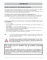
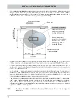
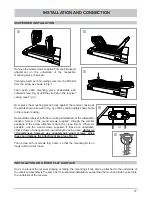
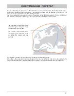
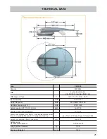
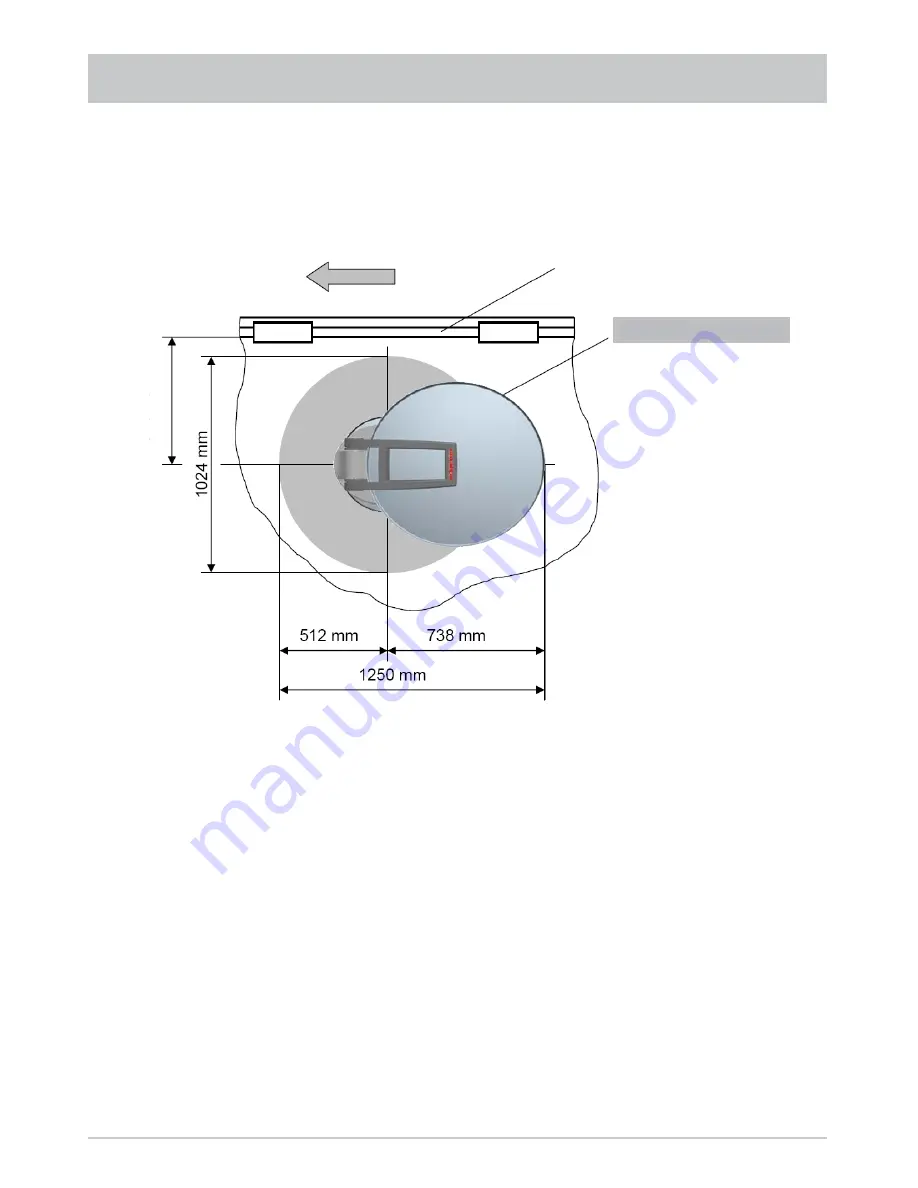
When selecting the installation position, take into account the range of movement of the turntable (see
the grey shaded area in the graphics). Within this grey area there must be no structures on the roof that
would obstruct this movement (risk of collision). For safety, keep at least the required area of 1024 x
1250 mm free (for ease of installation and any subsequent dismantling).
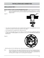
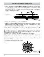
INSTALLATION AND CONNECTION
•
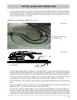
Choose a mounting position on the roof that is as fl at as possible, depending on the location of the
vehicle, since roof inclinations greater than 5° may lead to problems when searching for the satellite.
•
To ensure secure adhesion, the height difference of the roof curve may not be more than 1 cm over a
length of 2 m, as otherwise the gap between the roof and the mounting plate would be too great to be
fi lled by the adhesive sealant.
•
As the vehicle is constantly subjected to vibration loads during travel, the roof below the antenna unit
is also subject to signifi cant loads. Please note given the nature and capacity of your vehicle roof
(see also operating manual for the vehicle) that the weight of the antenna unit is approx. 19 kg. In case
of doubt, consult a qualifi ed dealer or your vehicle’s manufacturer.
•
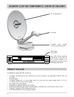
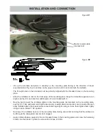
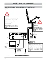
The roof gland provides a watertight seal through which the three connecting cables (2 x coax cables,
one x power supply cable) are fed into the interior of the vehicle directly underneath the turntable.
If you prefer a different method of laying the cables, they can be run from the rear of the turntable via
the channel provided in the mounting plate. The cables must then be run along the roof of the vehicle in
a protective cable duct (not supplied).
Note:
Do not cut the cables, as otherwise the proper functioning of the unit can no longer be
guaranteed.
Direction of travel
Roof rail
Turntable movement
range with antenna,
viewed from above
on the vehicle roof
Safety clearances
should be maintained
from the roof attach-
ments (e.g. due to
build-up of ice)
Height data under
“Technical Data”
min. 530 mm
Содержание MobiSet 4 digital CAP 900
Страница 1: ...Installation and operating manual Englisch MobiSet 4 digital CAP 900 ...
Страница 26: ...26 SIKAFLEX 291 DATA SHEET ...
Страница 27: ...27 SIKAFLEX 291 TECHNICAL DATASHEET ...
Страница 43: ...DECLARATION OF CONFORMITY ...


