


7
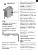
9 kW Saunaofen externe Steuerung
Terminal box
Sauna
heater foot
Screws M5 x 12 4x
2 x Wall bracket
4 x Securing
screws (wood
screws) 5 x 35
Screws 4 x
M5 x 12
Bottom panel
Self-tapping
screws 3.9 x 9.5
Note:
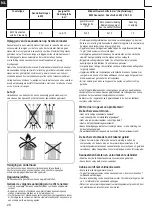
The control equipment may be destroyed even if it is incorrectly connected
only once. The warranty will be voided if the electrical connection is not
correct.
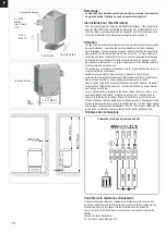
Instructions for the electrician
DIN VDE 0100 and Accident Prevention Regulation BGV A2 must be observed
for connecting the stove and all electrical systems. An external all-pole
disconnecting device with full isolation according to overvoltage category III must
be installed.
Important:
Mains connection leads must be
fl
exible cables with polychlorophene sheaths.
No connection leads are supplied with the stove. All the cables installed inside
the cabin must be suitable for an ambient temperature of at least 140°C. Heatre-
sistant silicon cables must be used. The minimum cross-section of the
connection cable and the minimum size of the sauna cabin are shown in the
table (Table 1 page 8). Make the electrical connection as shown in the
connection diagram . A connection diagram is additionally af
fi
xed to the inside of
the duct cover.
Fit the cover after making the electrical connection.
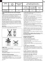
Please note that live cables must not be routed visibly on the internal walls of the
cabin for safety reasons. In prefabricated sauna cabins the wall element with the
air supply opening generally has empty cable conduits or a duct for routing the
cable.
If your cabin does not have any cable routing preparations, we recommend that
you install a connection socket (not supplied) to the outside of the cabin. Drill a
hole in the cabin wall near the cable infeed from the stove and the connection
socket. Thread the cable through the hole to the external connection socket.
Allcables must be protected from damage. This can be achieved using
installation ducting/piping or using wooden covers.
Connection diagram
Test the insulation resistance
The resistance values between the various conductor terminals and the case
(protective earth) can be measured using an insulation resistance measuring
unit. The total insulation resistance between the conductor terminals and case
(protective earth) must de
fi
nitely be greater than 1 MOhm.
Ohm values of the stoves
33 – 39
Ω
for 9 kW sauna heater
GB
Anleitung_ Saunaofen_37.468.25.indd 7
Anleitung_ Saunaofen_37.468.25.indd 7
11.02.15 15:42
11.02.15 15:42
Содержание Sauna 330
Страница 1: ...Sauna 330...
Страница 5: ...Sauna 330 1 6xM 6xM 3 xDET 1 2x DET A 3x DET 1 2xDET A 2800 1600 950 mm mm mm mm...
Страница 6: ...Sauna 330 2 I 1x DET 2 II 2 3a 3b 4 x DET 3a 4 x DET 3b X W Y Z mm mm 100mm 100 mm 3x M...
Страница 7: ...Sauna 330 3 I II 24x M...
Страница 8: ...Sauna 330 90 2x DET P 3A Bohren Sie 4 L cher in DET 2 10 mm...
Страница 11: ...6 I II 11x DET 5b 10x DET 5a 8x DET 3a 8x DET 3b 16xH 16xH 20xH Siehe Seite 6A Sauna 330...
Страница 17: ...Sauna 330 9 2xDET F 1xDET G 1xDET F 3x K 3x K 3x K 3x K...
Страница 18: ...Sauna 330 10 8x DET 7 24x H 575 I II 2xDET 8 2x DET 9...
Страница 19: ...Sauna 330 4xDET 10 Bitte bohren Sie 4mm L cher vor dem festschrauben 8x H 11 8x H 770 4x H...
Страница 23: ...Sauna 330 15 I r 300 10x H mm mm 2xDET 19 II...
Страница 24: ...Sauna 330 16 I 13x DET 20 II 26x H Entfernen DET A...
Страница 44: ...Karibu Artikel Nr Artikel Nr I Nr Typ 59319 37 468 25 11011 9 kW Saunaofen externe Steuerung...
Страница 45: ...2...
Страница 68: ...25...
Страница 75: ...ISC GmbH Art Nr 086 50 009 23 11011...
Страница 81: ...D 6 0 Wandmontage Steuerger t 2 St ck Schrauben 4 x 25 mm 1 St ck Schraube 4 x 25 mm...
Страница 87: ...D 080 000 000 020 000 000 OFF 70 OFF 70 Einstellung Beleuchtung...
Страница 91: ...D Ist eine Funktion inaktiv ist die LED dunkel 100 020 005 Ist eine Funktion aktiv dann leuchtet die LED ON 70...
Страница 95: ...D 13 0 Explosionszeichnung STG 2100 F STG 2100 F Art Nr 37 470 01 I Nr 18012...
Страница 96: ...D 13 1 St ckliste STG 2100 F I Nr 18012...
Страница 97: ...D STG 2100 FH Art Nr 37 470 11 I Nr 18012 13 2 Explosionszeichnung STG 2100 FH...
Страница 98: ...D 13 2 St ckliste STG 2100 FH I Nr 18012...
Страница 99: ...D...
Страница 102: ...D...
Страница 114: ...12 E Bedienung 3 080 000 000 000 020 000 000 000 ISC_STG2100_Anleitung_E indd 12 10 08 17 08 12...
Страница 115: ...13 E Bedienung 2 100 240 000 000 100 020 000 000 ISC_STG2100_Anleitung_E indd 13 10 08 17 08 12...
Страница 116: ...14 E Bedienung 2 100 240 095 000 100 020 060 000 ISC_STG2100_Anleitung_E indd 14 10 08 17 08 12...
Страница 122: ...20 E 13 0 Plano en expansi n STG 2100 F STG 2100 F Art Nr 37 470 01 ISC_STG2100_Anleitung_E indd 20 10 08 17 08 12...
Страница 124: ...22 E STG 2100 FH Art Nr 37 470 11 13 2 Plano en expansi n STG 2100 FH ISC_STG2100_Anleitung_E indd 22 10 08 17 08 12...
Страница 129: ...27 E ISC GmbH Art Nr 086 50 009 23 11011 Stand 02 2015 ISC_STG2100_Anleitung_E indd 27 10 08 17 08 12...
Страница 141: ...12 F Bedienung 3 080 000 000 000 020 000 000 000 ISC_STG2100_Anleitung_F indd 12 10 08 17 08 14...
Страница 142: ...13 F Bedienung 2 100 240 000 000 100 020 000 000 ISC_STG2100_Anleitung_F indd 13 10 08 17 08 14...
Страница 143: ...14 F Bedienung 2 100 240 095 000 100 020 060 000 ISC_STG2100_Anleitung_F indd 14 10 08 17 08 14...
Страница 149: ...20 F 13 0 Sch ma clat STG 2100 F STG 2100 F Art Nr 37 470 01 ISC_STG2100_Anleitung_F indd 20 10 08 17 08 14...
Страница 151: ...22 F STG 2100 FH Art Nr 37 470 11 13 2 Sch ma clat STG 2100 FH ISC_STG2100_Anleitung_F indd 22 10 08 17 08 14...
Страница 156: ...27 F ISC GmbH Art Nr 086 50 009 23 11011 Stand 02 2015 ISC_STG2100_Anleitung_F indd 27 10 08 17 08 14...
Страница 168: ...12 NL Bedienung 3 080 000 000 000 020 000 000 000 ISC_STG2100_Anleitung_NL indd 12 10 08 17 08 21...
Страница 169: ...13 NL Bedienung 2 100 240 000 000 100 020 000 000 ISC_STG2100_Anleitung_NL indd 13 10 08 17 08 21...
Страница 170: ...14 NL Bedienung 2 100 240 095 000 100 020 060 000 ISC_STG2100_Anleitung_NL indd 14 10 08 17 08 21...
Страница 176: ...20 NL 13 0 Explosietekening STG 2100 F STG 2100 F Art Nr 37 470 01 ISC_STG2100_Anleitung_NL indd 20 10 08 17 08 21...
Страница 178: ...22 NL STG 2100 FH Art Nr 37 470 11 13 2 Explosietekening STG 2100 FH ISC_STG2100_Anleitung_NL indd 22 10 08 17 08 21...
Страница 183: ...27 NL ISC GmbH Art Nr 086 50 009 23 11011 Stand 02 2015 ISC_STG2100_Anleitung_NL indd 27 10 08 17 08 21...


