


3
F
1.0 - Contenu de la livraison
(Sous réserve de modifications techniques)
Les composants suivants sont compris dans la livraison de l’appareil de commande :
1. Appareil de commande avec panneau de commande et élément de charge intégré
2. Capteur avec sonde de poêle et fusible de température
3. Capteur avec sonde de température / sonde d’humidité
4. 2 boîtiers de sonde
5. 1 câble de sonde en silicone à 3/4 fils d’env. 5 m. de long
6. Sac de montage (3 vis 4 x 40 mm et 4 vis 3 x 30 mm)
2.0 - Caractéristiques techniques
Dimensions du boîtier
Largeur 235 mm -Hauteur 195 mm – Profondeur 75 mm
Commande
Zone tactile – Commande tactile
Affichage
4 zones de 15 mm x 30 mm
Type de protection
IPX4
Tension nominale
400 V ~ 3 N PE
Puissance de commutation mode finlandais Maximum 10,8 kW charge résistive (mode AC1)
Puissance de commutation mode humidité Maximum 9,3 kW plus 1,5 kW pour unité de bio évaporateur
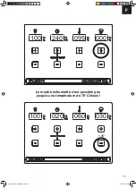
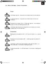
Plage de réglage mode finlandais
5° à 100° Celsius - Réglage par 5°
Plage de réglage mode bio
5° à 70° Celsius - Réglage par 5°
Limitation de sonde de poêle
125° Celsius (sonde de poêle n°1)
Limitation de température
140° Celsius (sonde de poêle n°1)
Affichage de la température
Maximum 110° Celsius (point RAL sonde n°2)
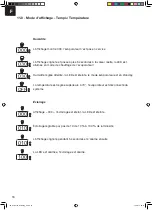
Affichage de l’humidité
Maximum 95 % (point RAL sonde n°2)
Commande d’humidité
Mesure par sonde d’humidité - Mesure réelle
Présélection du temps
Maximum 240 minutes ou 4 heures - Réglage par 20 min.
Limitation de temps de chauffe
240 minutes ou 4 heures
Éclairage
Maximum 60 watts – Variable réglage par 10 %
Températures ambiantes
-15° à +40° Celsius
Zone extérieure
Boîtier de protection nécessaire (protégé contre les
projections d’eau)
3.0 - Explication des symboles
Information !
Donne à l’utilisateur des conseils et des informations utiles sur la commande et l’utilisation
de l’installation de sauna (cabine de sauna, poêle de sauna, commande de sauna) !
Avertissement !
Indications d’éventuels risques, situations dangereuses ou risque de blessure !
Danger !
Indications d’éventuels risques, situations dangereuses pouvant conduire au décès !
Attention !
Indications qui, en cas de non-respect, peuvent entraîner des pannes ou endommager les
composants.
Tension électrique !
Mise en garde contre la tension et la haute tension ! Un non-respect peut entraîner des
décharges électriques.
ISC_STG2100_Anleitung_F.indd 3
10.08.17 08:14
Содержание Sauna 330
Страница 1: ...Sauna 330...
Страница 5: ...Sauna 330 1 6xM 6xM 3 xDET 1 2x DET A 3x DET 1 2xDET A 2800 1600 950 mm mm mm mm...
Страница 6: ...Sauna 330 2 I 1x DET 2 II 2 3a 3b 4 x DET 3a 4 x DET 3b X W Y Z mm mm 100mm 100 mm 3x M...
Страница 7: ...Sauna 330 3 I II 24x M...
Страница 8: ...Sauna 330 90 2x DET P 3A Bohren Sie 4 L cher in DET 2 10 mm...
Страница 11: ...6 I II 11x DET 5b 10x DET 5a 8x DET 3a 8x DET 3b 16xH 16xH 20xH Siehe Seite 6A Sauna 330...
Страница 17: ...Sauna 330 9 2xDET F 1xDET G 1xDET F 3x K 3x K 3x K 3x K...
Страница 18: ...Sauna 330 10 8x DET 7 24x H 575 I II 2xDET 8 2x DET 9...
Страница 19: ...Sauna 330 4xDET 10 Bitte bohren Sie 4mm L cher vor dem festschrauben 8x H 11 8x H 770 4x H...
Страница 23: ...Sauna 330 15 I r 300 10x H mm mm 2xDET 19 II...
Страница 24: ...Sauna 330 16 I 13x DET 20 II 26x H Entfernen DET A...
Страница 44: ...Karibu Artikel Nr Artikel Nr I Nr Typ 59319 37 468 25 11011 9 kW Saunaofen externe Steuerung...
Страница 45: ...2...
Страница 68: ...25...
Страница 75: ...ISC GmbH Art Nr 086 50 009 23 11011...
Страница 81: ...D 6 0 Wandmontage Steuerger t 2 St ck Schrauben 4 x 25 mm 1 St ck Schraube 4 x 25 mm...
Страница 87: ...D 080 000 000 020 000 000 OFF 70 OFF 70 Einstellung Beleuchtung...
Страница 91: ...D Ist eine Funktion inaktiv ist die LED dunkel 100 020 005 Ist eine Funktion aktiv dann leuchtet die LED ON 70...
Страница 95: ...D 13 0 Explosionszeichnung STG 2100 F STG 2100 F Art Nr 37 470 01 I Nr 18012...
Страница 96: ...D 13 1 St ckliste STG 2100 F I Nr 18012...
Страница 97: ...D STG 2100 FH Art Nr 37 470 11 I Nr 18012 13 2 Explosionszeichnung STG 2100 FH...
Страница 98: ...D 13 2 St ckliste STG 2100 FH I Nr 18012...
Страница 99: ...D...
Страница 102: ...D...
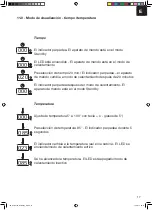
Страница 114: ...12 E Bedienung 3 080 000 000 000 020 000 000 000 ISC_STG2100_Anleitung_E indd 12 10 08 17 08 12...
Страница 115: ...13 E Bedienung 2 100 240 000 000 100 020 000 000 ISC_STG2100_Anleitung_E indd 13 10 08 17 08 12...
Страница 116: ...14 E Bedienung 2 100 240 095 000 100 020 060 000 ISC_STG2100_Anleitung_E indd 14 10 08 17 08 12...
Страница 122: ...20 E 13 0 Plano en expansi n STG 2100 F STG 2100 F Art Nr 37 470 01 ISC_STG2100_Anleitung_E indd 20 10 08 17 08 12...
Страница 124: ...22 E STG 2100 FH Art Nr 37 470 11 13 2 Plano en expansi n STG 2100 FH ISC_STG2100_Anleitung_E indd 22 10 08 17 08 12...
Страница 129: ...27 E ISC GmbH Art Nr 086 50 009 23 11011 Stand 02 2015 ISC_STG2100_Anleitung_E indd 27 10 08 17 08 12...
Страница 141: ...12 F Bedienung 3 080 000 000 000 020 000 000 000 ISC_STG2100_Anleitung_F indd 12 10 08 17 08 14...
Страница 142: ...13 F Bedienung 2 100 240 000 000 100 020 000 000 ISC_STG2100_Anleitung_F indd 13 10 08 17 08 14...
Страница 143: ...14 F Bedienung 2 100 240 095 000 100 020 060 000 ISC_STG2100_Anleitung_F indd 14 10 08 17 08 14...
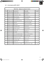
Страница 149: ...20 F 13 0 Sch ma clat STG 2100 F STG 2100 F Art Nr 37 470 01 ISC_STG2100_Anleitung_F indd 20 10 08 17 08 14...
Страница 151: ...22 F STG 2100 FH Art Nr 37 470 11 13 2 Sch ma clat STG 2100 FH ISC_STG2100_Anleitung_F indd 22 10 08 17 08 14...
Страница 156: ...27 F ISC GmbH Art Nr 086 50 009 23 11011 Stand 02 2015 ISC_STG2100_Anleitung_F indd 27 10 08 17 08 14...
Страница 168: ...12 NL Bedienung 3 080 000 000 000 020 000 000 000 ISC_STG2100_Anleitung_NL indd 12 10 08 17 08 21...
Страница 169: ...13 NL Bedienung 2 100 240 000 000 100 020 000 000 ISC_STG2100_Anleitung_NL indd 13 10 08 17 08 21...
Страница 170: ...14 NL Bedienung 2 100 240 095 000 100 020 060 000 ISC_STG2100_Anleitung_NL indd 14 10 08 17 08 21...
Страница 176: ...20 NL 13 0 Explosietekening STG 2100 F STG 2100 F Art Nr 37 470 01 ISC_STG2100_Anleitung_NL indd 20 10 08 17 08 21...
Страница 178: ...22 NL STG 2100 FH Art Nr 37 470 11 13 2 Explosietekening STG 2100 FH ISC_STG2100_Anleitung_NL indd 22 10 08 17 08 21...
Страница 183: ...27 NL ISC GmbH Art Nr 086 50 009 23 11011 Stand 02 2015 ISC_STG2100_Anleitung_NL indd 27 10 08 17 08 21...


