9
GB
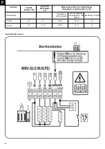
Connection rating
cabine size
4,5 kW
9,0 kW
< 7 m
3
6 - 14 m
3
General:
Dear Customer,
Please read these operating instructions carefully before you connect and use
the sauna stove for the
fi
rst time to prevent causing any damage.
Important safety instructions
• The sauna heater is a subassembly and is therefore
independent, meaning that without a suitable control
system it will not fully meet the requirements of the
applicable standards.
• The sauna heater may only be connected to and
operated by an approved sauna control system with
a thermal cut-out for 140°C, otherwise there will be a
serious risk of
fi
re.
• The sauna heater may only be installed by a quali
fi
ed
electrician and in this connection EN 60335-2-53 and
requirements with respect to installation and
fi
re pro-
tection measures applicable at the place of use must
be complied with.
• The sauna heater is for private household use only,
a remote control is not permitted and covered ins-
tallation is not permitted. Use only approved control
systems with a thermal cut-out (140°C) in accordance
with EN 60335-2-53.
• For the use of the sauna heater, an approved control
system in accordance with EN 60335-2-53 must be
used. The control system must meet the following
requirements as a minimum:
• The control system must limit the temperature of the
sauna cabin to 135°C. A thermal cut-out which meets
these requirements must be integrated in the sauna
control system which is used, otherwise there will be a
serious risk of
fi
re.
• This control system must have an integrated timer
which limits the operating period to a maximum of 6
hours, with automatic restart not permitted.
For sauna heaters with an integrated additional vapori-
zer, only an approved sauna control system in accor-
dance with EN 60335-2-53 which also has a humidity
controller is allowed to be used.
•
Sauna heater for private household use, remote con-
trol not permitted, covered installation not permitted,
use only suitable control units with thermal cut-outs
in accordance with the information provided by the
manufacturer.
• The installation and electrical connection of the sauna
equipment and other
electrical equipment may only be carried out by a
licensed electrician. (except P & P)
• Refer to the safety actions required by VDE 0100 § 49
DA/6 and VDE 0100 Part 703/11.82 §4. Even if you
comply with the required safety actions it is not
possible to rule out the possibility of all accident risks.
• Follow the safety instructions to the letter to ensure
that you can operate your equipment safely.
• The sauna stove must be operated with a suitable
external control unit.
• The bio sauna stove requires a sauna controller with
a humidity module or a separate additional humidity
controller to activate the evaporator. Instructions
for installing and operating these units are provided in
the manual supplied with the respective controller.
• Only one sauna stove with the appropriate heating
capacity may be installed in the sauna cabin.
(See table)
• The equipment does not have approval for use in
commercial saunas and apartment blocks.
• Caution – danger of burns. The case on the sauna
stove and the stones get very hot.
• If it is not installed correctly the unit may cause a
fi
re.
Read the complete assembly instructions with due
care. Pay particular attention to the dimensions and
instructions.
• Only use sauna stones approved for use in saunas.
Insert sauna stones loosely; if the stones are inserted
too tightly there is a danger of overheating.
Karibu_Anl._ Bio-Saunaofen_37.468.30.indd 9
Karibu_Anl._ Bio-Saunaofen_37.468.30.indd 9
13.05.20 16:57
13.05.20 16:57
Содержание 80910
Страница 9: ...15 1 Ø3mm 5x 13 13 1 13 1 15 14 B 1 M 2 M 1 M 3 B 1 Ø3mm 4x70 15 1 4x 4 70 19x 4x70 ...
Страница 13: ...B 10 B 8 26 25 4 50 Ø3mm 27 4 50 8x 4 50 5x 4 50 B 11 Ø3mm L 2 28 2x 4x35 B 6 B 6 B 5 Ø3mm B 5 4 30 16x ...
Страница 23: ...08 1 2 3 ...
Страница 68: ...45 Ersatzteilzeichnung ...
Страница 70: ...47 ...
Страница 80: ... B C I G 5 5 5 5 C I R R P R R R C I R R R C I P 1 P C I 1 1 C I 1 1 5 C I G G 1 I G 1 G 5 5 5 57 ...
Страница 82: ...59 ...
Страница 83: ... ISC GmbH Art Nr 086 50 006 76 11031 Stand 05 2020 ...
Страница 89: ...6 D 6 0 Wandmontage Steuergerät 2 Stück Schrauben 4 x 25 mm 1 Stück Schraube 4 x 25 mm ...
Страница 90: ...7 D 7 0 Steuergeräte Ausführungen 50 50 70 ...
Страница 97: ...14 D Einstellung Beleuchtung 50 70 50 70 050 ...
Страница 98: ...15 D Einstellung Start Stop und Taste gleichzeitig mit Zeige und Mittelfinger betätigen 50 70 50 70 ...
Страница 99: ...16 D Einstellung Temperatur 50 70 50 70 ...
Страница 100: ...17 D Einstellung Feuchte 50 70 50 70 ...
Страница 101: ...18 D 50 70 ...
Страница 116: ...33 GB Adjusting the lighting 50 70 50 70 050 ...
Страница 120: ...37 50 70 GB When a function is active the LED will be illuminated When a function is inactive the LED will be dark ...
Страница 135: ...52 50 70 50 70 050 F Réglage de l éclairage ...
Страница 139: ...56 50 70 F Si une fonction est active la LED est allumée Si une fonction est inactive la LED est éteinte ...
Страница 154: ...71 50 70 50 70 050 I Regolazione dell illuminazione ...
Страница 158: ...75 50 70 I Se una funzione è attiva il LED è illuminato Il LED è spento se una funzione non è attiva ...
Страница 173: ...90 50 70 50 70 050 Regulación de la iluminación E ...
Страница 177: ...94 50 70 Si una función está activa se enciende el LED Si una función está inactiva el LED está oscuro E ...
Страница 189: ...106 NL Verlichting Licht Netaansluiting Kachelaansluiting Voeler 1 Voeler 2 9 2 Sauna Control FIN P P aansluitschema ...
Страница 190: ...107 NL Verlichting Licht Netaansluiting Kachelaansluiting Voeler 1 Voeler 2 9 3 Sauna Control BIO P P aansluitschema ...
Страница 192: ...109 D 50 70 50 70 050 NL Instelling verlichting ...
Страница 196: ...113 D 50 70 NL Als een functie actief is dan brandt de LED Als een functie niet actief is dan is de LED donker ...
Страница 208: ...125 CZ 9 2 Sauna Control FIN P P schéma zapojení Osvětlení světlo Síťová přípojka Přípojka kamen Čidlo 1 Čidlo 2 ...
Страница 209: ...126 CZ 9 3 Sauna Control BIO P P schéma zapojení Osvětlení světlo Síťová přípojka Přípojka kamen Čidlo 1 Čidlo 2 ...
Страница 211: ...128 50 70 50 70 050 CZ Nastavení osvětlení ...
Страница 220: ...137 D 13 1 Stückliste Sauna Control FIN Sauna Control FIN Artikelnummer 37 470 01 I Nr 18012 ...
Страница 222: ...139 D 13 3 Stückliste Sauna Control BIO Sauna Control BIO Artikelnummer 37 470 11 I Nr 18012 ...
Страница 223: ...140 13 4 Explosionszeichnung Sauna Control FIN P P Sauna Control FIN P P Art Nr 37 470 02 I Nr 19011 ...
Страница 225: ...142 13 6 Explosionszeichnung Sauna Control BIO P P Sauna Control BIO P P Art Nr 37 470 12 I Nr 19011 ...
Страница 231: ...148 CZ ...
Страница 237: ...154 D Stand 03 2019 ...


