


Karel MS26s Installation & Maintenance Guide
Edition 3.1
13
•
S
IGNALING AND
C
OMMUNICATION
P
ARAMETERS
:
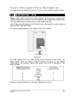
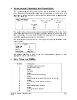
The signaling between the system and the PC is illustrated in the following
table. Since the PC-Exchange cable has a 25-pin plug at the PC end, it is
necessary to employ a 25-pin to 9-pin converter plug, in order to use the 9-pin
connector of the PC:
MB26s Motherboard
PC
CM Socket Pin No
Signal
25-pin Connector
Pin No
9-pin Connector
Pin No
1 PC
GND 7
5
2 TXD 3
2
3 RXD 2
3
4 Busy -
-
The signal names above are given with respect to MS26s system and these
pin assignments are valid only for IBM compatible devices. If your device is not
IBM compatible, then you must provide the requested pin connections to
match the signaling parameters of the system.
The communication protocol for PC - Exchange connection is illustrated in the
following table:
For PC
Data Bits
8
Stop Bit
1
Parity
None
Baud Rate
4800 Bps
The CM26s interface is able to set the communication protocol to the
appropriate values, automatically.
•
D
ATA
F
ORMAT OF
CM26
S
:
Field No
Information
1
#; indicates start of record
2
4 digit counter value
3 Space
4 Call
type
5 Space
6
Date in the format dd/mm/yy
7 Space
8
Starting time of the call in the format hh:mm:ss
9 Space
10
Call duration in the format hh:mm:ss
11 Space
12
Starting extension number
13 Space
14
Ending extension number
15 Space
Содержание MS26S
Страница 1: ...Karel MS26s T e l e p h o n e S y s t e m Installation Maintenance Guide Edition 3 1...
Страница 2: ......
Страница 6: ......
Страница 7: ...TECHNICAL REFERENCE...
Страница 8: ......
Страница 14: ......
Страница 28: ......
Страница 32: ......
Страница 33: ...INSTALLATION GUIDE...
Страница 34: ......
Страница 36: ......
Страница 42: ...Karel MS26s Installation Maintenance Guide Edition 3 1 34 Figure B 7...
Страница 60: ...Karel MS26s Installation Maintenance Guide Edition 3 1 52 Figure B 27...
Страница 61: ......
Страница 62: ...Design and specifications subject to change without notice...