


Karel MS224 Installation & Maintenance Guide
Edition 3.2
15
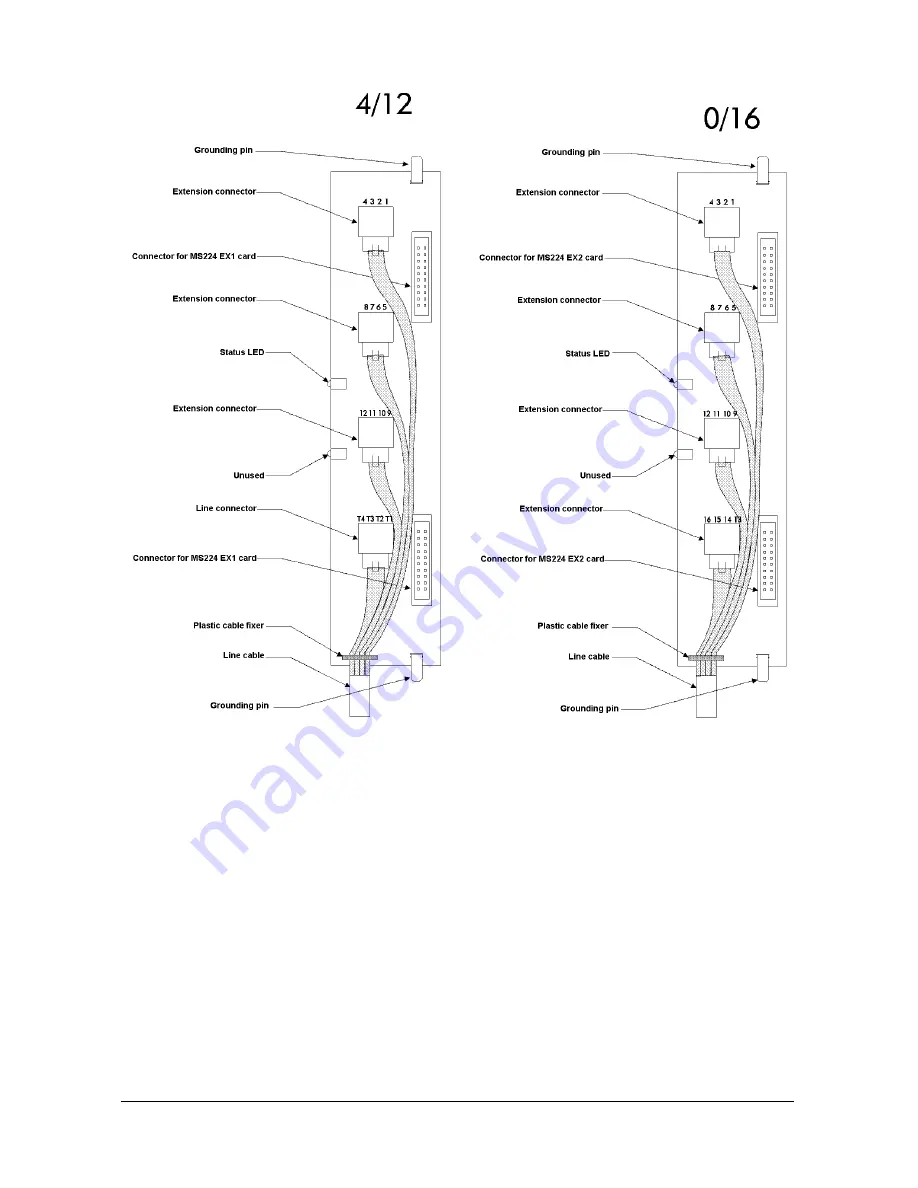
Figure A-9
CON1 lays on the component side of MS224 EX1B, in such a way that the two 20-
pin connectors on component side of CON1 are attached to the corresponding
connectors on the component side of MS224 EX1B. The same also applies to the
connection of CON2 and MS224 EX2B. The pin-outs of the CON1 – MS224 EX1B
and CON2 – MS224 EX2B connectors are illustrated in the following tables :
Содержание MS224
Страница 1: ...Karel MS224 T e l e p h o n e S y s t e m Installation Maintenance Guide Edition 3 2...
Страница 5: ......
Страница 23: ......
Страница 43: ......
Страница 47: ......
Страница 52: ...Karel MS224 Installation Maintenance Guide Edition 3 2 49 Figure B 4 Figure B 5...


