-
2
* Order no. 3.631-039.0
** Order no. 3.631-058.0
* Order no. 3.631-039.0
** Order no. 3.631-058.0
A locking screw is required for 1 nozzle op-
eration (see accessories).
* Standard
Note:
The use of a dirt filter in the high-
pressure line is recommended, but the
sieve should be cleaned regularly.
DANGER
Risk of fatal injuries on account of electric
voltage! Required electrical work must only
be performed by an electrical specialist.
– The socket must be secured through a
residual current device (RCD) with a
triggering current of 30 mA.
– This socket must be located close to the
work station so that the plug can be
pulled immediately in case of an emer-
gency.
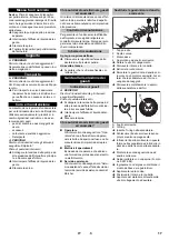
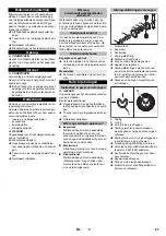
1 Screwed sealing plug
2 Bevel wheel
3 Axle stub
4 Drum screws or hole cone
Loosen the locking screw.
Remove the disc and the circular blank.
Pull off the bevel wheel.
Unscrew axel stub by means of a round
tool (2.8 mm diameter).
Insert or replace drum screws or hole
cone.
Coat the axle stub with sealant (Loctite
no. 500, order no. 6.869-002) and
screw it in.
Attach bevel wheel.
Mount the disc and the circular blank.
Lubricate locking screw with sealant
and screw it in.
DANGER
Risk of injury on account of the escaping
water jet that could be hot!
–
Only use the interior cleaner in closed
containers.
–
Only insert the interior cleaner into a
container or switch it into another con-
tainer while the separate high pressure
pump and internal drive are turned off.
Note:
Try to arrange the interior cleaner
centrally.
Screw the interior cleaner onto the ob-
ject to be cleaned using the screw con-
nection on the support pipe; or, with the
hole cone model, insert and adjust the
immersion depth.
Connect the high pressure pump to the
interior cleaner via a high pressure
hose.
Plug in the mains plug.
Open the cleaning liquid supply.
Switch on the separate high pressure
pump.
Note:
With almost all cleaning tasks, 2 noz-
zles will achieve a good cleaning result.
With very large and extremely dirty contain-
ers, 1 nozzle is used; the other one is
locked with a screw.
Advantage:
– Better cleaning result by larger spray
width and impact force of the cleaning
jet.
Disadvantage:
– The bearings and seals are stressed
more and will wear faster.
– Extension of the cleaning time.
Technical specifications
HKF 50 M
Max. flow rate
l/h (l/
min)
1200 (20)
Max. temperature of
the cleaning liquid
°C
85
Max. operating pres-
sure
MPa
(bar)
15 (150)
Max. overpressure
MPa
(bar)
18 (180)
Voltage
V
230
Current type
--
1~
Frequency
Hz
50
Rated power
W
40
Type of protection
--
IPX5
Functional speed -
drive
1/min
11
High pressure con-
nection
--
M22x1.5
Minimum container
opening
mm
50
Total length
mm
mm
1265 *
575 **
Max. immersion
depth
mm
mm
850 *
160 **
Weight
kg
kg
7.8 *
4.3 **
Ambient tempera-
ture
°C
+2...+40
Dimensional sheet HKF 50 M
1095 * / 405 **
1265 * / 575 **
850 * / 160 **
Selecting the nozzle
1 nozzle operation
Flow volume [l/
h]
1200
600
1000
Pressure [MPa]
10
6.5
10
Nozzle size
0009
00055 0007
Order no.
6.415-
447
445
077
2 nozzle operation
Flow volume [l/h]
1200
960
Pressure [MPa]
10
14
Nozzle size
00045 0003
Order no. 6.415-
446
444 *
Start up
Electric drive
Attach drum screws or hole cone
Operation
8
EN
Содержание HKF 50 M
Страница 2: ...2...
Страница 49: ...3 30 K rcher Kaercher 1 2 3 4 A B 5 901 068 49 EL...
Страница 57: ...3 K rcher K rcher 1 2 3 4 A B 5 901 068 57 RU...
Страница 93: ...3 30 K rcher Karcher 1 2 3 4 A B 5 901 068 T o 93 BG...
Страница 109: ...3 30 K rcher K rcher 1 2 3 4 A B 5 901 068 109 UK...
Страница 111: ......


