background image

Congratulations! 


The LASER 2000 is one of the finest ARF high performance models available. Originally 

designed as a competition aircraft, It has proven itself time and time again in the winner circle. All the 
great flying characteristics have been retained, along with all the special design features of a full bread 
competitor. The tail surfaces are removable for shipping. The flying wires are functional. Several servo 
and engine options are available to suit you personal needs and the highest quality hardware available 
has been included. When properly assembled if can perform anything in the current realm of I.M.A.C or 
T.O.C high Alfa maneuvers. 


WARNING! 

As model aircraft get larger and more powerful, the risk for injury increases. 

KANGKE’s extensive testing procedures insure a high quality kit that has gone through many steps to 
provide you with a safe reliable airframe. Nothing we can do however will make up for poor assembly 
or irresponsible behavior at the field. A model this size and weight traveling at 80 MPH contains enough 
energy that if it were to contact another person, the injuries would be extensive possibly fatal. The safe 
operation of this model is yours and yours alone. If you are a beginner or have never flown a model of 
this size and power, you should 

not

 make the attempt without the help of an experienced pilot. 


Enjoy this aircraft, you may never find one that flies better! 
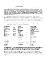


Specifications: 
Length  70 

in. 

Wing span 


87 in. 

Wing area wet 

1204 sq. 

in. 
Surface area   

1421 sq. 

in. 
Weight  16-18 

lbs. 

Wing load 


27-29 oz. 

Engine  2.4-3.2 
C.I. Gas 
 
Kit Contents: 
Fuselage  


Wing panel   

Ailerons   2  
Cowling   1 
Canopy   1 
Main gear 


Stabilizer  

Elevator half   

Rudder   1 
Fin 

  1 

Servo mount   

Fuel tank 


Wheels  2 
Tail wheel 


   Control horns 

Control rods   

Hardware pack 

Wheel pants   

Set flying wires 

Wing tube 


The following items will also 
be needed to assemble your 
LASER 2000: 
 

Hobby 

Items: 


30-min. 

epoxy   

Hobby 

Knife 


4-6channel radio 


Gas 

line    

5 heavy duty servos   


Engine 


Med. CA 1-oz. 


Muffler    
 
Household Items: 
Paper towels 
Alcohol 
Popsicle sticks 
Felt tip pen 
Screwdrivers 
Wax paper 
Pliers 
String 

 
If you are familiar with the assembly of ARF type aircraft, you will find the assembly sequence to 
seem out of order. This is because of some of the unusual features of a competition airframe. 
Please follow the sequence as written. The Laser 2000 will take 20-25 hours to complete. 
 
Read each step of the assembly carefully. Be sure you understand what is required for each 
procedure before you glue of cut anything. How well you assemble this model will have a direct 
effect on its flight characteristics. Do not omit any steps. Take your time and enjoy the building 
process. 


Содержание LASER 2000

Страница 1: ...ranty does not cover any parts damaged by use or modifications In no case shall Kangke Industrial s liability exceed the purchase cost of this kit Since Kangke Industrial has no control of final assembly and material used by user for final assembly no liability shall be assumed or accepted for any damage resulting from the use by user of final user assembled products This kit has been flight test ...

Страница 2: ...n a model of this size and power you should not make the attempt without the help of an experienced pilot Enjoy this aircraft you may never find one that flies better Specifications Length 70 in Wing span 87 in Wing area wet 1204 sq in Surface area 1421 sq in Weight 16 18 lbs Wing load 27 29 oz Engine 2 4 3 2 C I Gas Kit Contents Fuselage 1 Wing panel 1 Ailerons 2 Cowling 1 Canopy 1 Main gear 1 St...

Страница 3: ...Install the stabilizer hold down screws for alignment do not tighten Use a felt tip marker to outline the rudder support block on the side of the fin With a sharp hobby blade and a straight edge slice the covering inch below the marked line Be careful not to slice into the wood as that would weaken the structure Peel away the covering a shown Apply a thin coat of epoxy to the inside of the rudder ...

Страница 4: ...ngine The distance from the back of the spinner to the firewall must be at least 6 7 16 inches for proper clearance with the cowl The BRISON 2 4 used on the prototype required a 1 1 8 inch spacer The size of the spacer you need will depend on your choice of engine When installing the tail surfaces for use apply a thin bead of RTV silicone to the stabilizer rudder support mating surface Install the...

Страница 5: ...forward Install the tail wheel bracket Align the tail wheel pivot hole with the back edge of the rudderpost The airframe can now stand on its gear allowing clearance for the cowl Temporarily install the canopy deck Line up the cowl and open any holes that are necessary for engine exhaust clearance Locate the holes for the cowl mount Remove the cowl and deck Assemble the gas tank Be sure the flop t...

Страница 6: ...tion such as the BRISON 3 2 you may wish to slide the tank to the side to allow room for the module and battery You will have to cut a small notch in the bottom of the canopy deck directly over the tank for clearance Using a 1 8 inch drill locate and drill the holes for the control horns in the rudder and elevators Use the dimensions below notice that the horn backing ring touches the back of the ...

Страница 7: ... servos The elevator servos must have at least 60 oz of torque the prototype used HITEC HS625BBMG The rudder must have at least 100 oz of torque the prototype used HITEC HS645BBMG Install and adjust the supplied elevator control rods Fabricate the rudder pull pull using the supplied rods Remove the servo covers from the wing halves Open the slot for the servo horn Install the servo in the servo co...

Страница 8: ...porarily install the wing panels Locate and drill a hole for the plastic outer throttle push rod Locate and mount the throttle servo and bracket inside the fuselage Be sure the servo and push rod do not interfere with the wing attach bolts Slide the axle through the recessed side of the wheel Slide a collar on and tighten the set screw leave enough play so thee tire spins freely Install the anti r...

Страница 9: ...his location will provide the most stability As your comfort and skill increase slowly move the C G aft to increase the control response The recommended starting range for the C G is 5 3 8 inches to 5 3 4 inches back from the leading edge of the wing measured against the side of the fuselage 5 inches is 27 of the MAC mean aerodynamic chord Slide the battery pack to a position where the plane will ...

Страница 10: ...ith the airplane flying away from you adjust the rudder trim till the fuselage tracks straight it may be necessary to correct the aileron trim after this procedure Continue to fly and trim until the aircraft is tracking well land before the fuel runs out Carry a little power on final approach until over the end of the runway then cut power to idle hold the plane just off the runway till the airspe...

Страница 11: ...f down elevator is required to maintain a straight line shim the back of the main wing 1 8 inch at a time till the elevator is neutral If up elevator is required shave the rear of the wing saddle 1 8 inch at a time Engine Thrust Angle Up Down On a low pass 50 power crosswind go to 80 power and pull vertical at the same time As the model slows do not correct path with elevator If the model tries to...

Отзывы: