

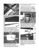


Bend all the flying wire attach brackets to a
45-degree angle and install in the fin and
stabilizer as shown. Tighten the screws only to
the point where the stabilizers wood begins to
crush, do not over tighten. A small dab of RTV
silicone will prevent them from vibrating loose.
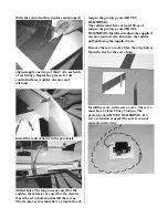
Measure the firewall across the top and
bottom, locate and draw the vertical
centerline. Measure down 1 3/8-inches from
the top of the firewall and draw a horizontal
line. Where the lines cross should be the center
of the crankshaft of the engine.
The distance from the back of the spinner to
the firewall must be at least 6 7/16-inches for
proper clearance with the cowl. The BRISON
2.4 used on the prototype required a 1 1/8-inch
spacer. The size of the spacer you need will
depend on your choice of engine.
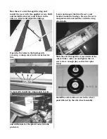
When installing the tail surfaces for use apply
a thin bead of RTV silicone to the stabilizer
rudder support-mating surface. Install the
flying wire attach bracket ¾-inch behind the
rudder servo opening as shown.
Install the flying wires on the bottom of the
stabilizer. The short wires in the front, the
long wires in the rear. Square the stabilizer by
adjusting the wire tension.
NOTE
: Do not over
tighten the wires, excess tension may distort
the stabilizer.


