background image

Venkon XL

Beschreibung

Assembly, installation and operating instructions

43

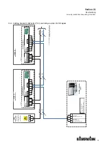
7.4.2 Connection (*C1)

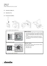
Wrong!

Star-shaped wiring of the bus lines.

General information

Route all low voltage cables along the shortest route.
Ensure that low-voltage and power cables are separated, using
metal partitions on cable harnesses.
Use only shielded cables as low-voltage and bus cables.
Lay all BUS cables in a linear pattern. Star-shaped wiring is not
permitted.
The KaController is connected via a bus connection to the respect-
ive control PCB on the unit.

Right!

Linear wiring of the bus lines.

Tab. 12: Wiring of bus lines

IMPORTANT NOTE!

Use shielded, paired cables as bus cables, UNITRONIC® BUS LD 2x2x0.22, but at least of the same value or
higher.

IMPORTANT NOTE!

When laying bus cables, avoid the formation of star points, for instance in junction boxes. Loop the cables
through to the units!

Содержание Venkon XL

Страница 1: ...Venkon XL Assembly installation and operating instructions Keep these instructions in a safe place for future use Issue02 20EN SAP No 1374732...

Страница 2: ......

Страница 3: ...5 Construction and function 14 5 1 Overview 14 5 2 Brief description 14 5 3 Wear parts list 14 6 Installation and wiring 15 6 1 Definition of the connection side 15 6 2 Requirements governing the ins...

Страница 4: ...43 7 4 3 Cabling Venkon XL KaControl C1 control by on site 0 10 V DC signal 45 7 4 4 Cabling Venkon XL KaControl C1 control by KaController 46 8 Pre commissioning checks 47 9 Operation 49 9 1 Operatio...

Страница 5: ...5 13 2 ERP Datenblatt Venkon XL 70...

Страница 6: ...ations apply as do general safety provisions governing the use of the equipment Illustrations in this guide are intended to provide a basic understanding and may differ from the actual model Ongoing t...

Страница 7: ...of use described in Chapter 2 2 8 must be complied with IMPORTANT NOTE Only use the unique after completion of the complete building and system Site heating is not deemed to be correct and proper use...

Страница 8: ...would refer to VDI 2035 Sheets 1 2 DIN EN 14336 and DIN EN 14868 with regard to the properties of the medium used to protect the equipment The following values provide further guidance The water used...

Страница 9: ...s e g sea air Never operate the unit above electrical equipment such as switch cabinets computers or other electrical units or contacts that are not drip proof IMPORTANT NOTE Energy losses due to misu...

Страница 10: ...ent prevention regulations Guidelines and recognised technical regulations i e Association of German Electricians VDE regulations DIN and EN standards VDI 6022 Maintenance personnel must be trained to...

Страница 11: ...n website IMPORTANT NOTE 2 people are needed to transport the unit Wear personal protective clothing when transporting the unit Only lift the unit on both sides and not by the pipes valves IMPORTANT N...

Страница 12: ...vibrations and shocks IMPORTANT NOTE Under certain circumstances packages can carry storage instructions that go beyond the requirements listed here Comply with these instructions accordingly 3 4 Pack...

Страница 13: ...9 Internal volume of 4 pipe system cooling l 1 4 2 8 4 2 5 7 Connection size 2 pipe Rp 3 4 Rp 3 4 Rp 3 4 Rp 3 4 Connection size 4 pipe heating Rp 1 2 Rp 1 2 Rp 1 2 Rp 1 2 Connection size 4 pipe coolin...

Страница 14: ...ls offices and business premises among others Secondary air is drawn in filtered by the fan and passed through the copper aluminium heat exchanger Here the air is either heated or cooling depending on...

Страница 15: ...connection on right Venkon XL with flexible connection unit connection on right Side view connection side Side view connection side Connection on left Connection on right View of air inlet side View o...

Страница 16: ...ate space for flow and return water connections on site Chapter 6 5 1 Connection to the pipe network There is a power supply on site Maximum electrical rating values 33 If need be provide a condensati...

Страница 17: ...ation IMPORTANT NOTE Avoid draughts Consider the occupied zone when installing suspending the units Do not expose people to the direct air flow Position the unit accordingly and adjust the air outlet...

Страница 18: ...nd the unit using the suspension and connecting brack ets to on site suspensions recommended M8 threaded rod with washer and nut Fig 6 Adjusting the suspension Level the unit and if need be adjust it...

Страница 19: ...Figure Description Dimensions mm 500 900 1300 1700 275 275 Connection unit for circular pipe with DN 200 spigot Model 1 500 Model 2 900 Model 3 1300 Model 4 1700 Tab 6 Air side sheet steel accessories...

Страница 20: ...ets 2 no with model 2 4 no with model 3 and model 4 on the air outlet side at the top and bottom Fig 10 Positioning the connection unit Position the connection unit in front of the air outlet and manu...

Страница 21: ...accessible through one of the spigots Fig 13 Tightening screws internally Use a suitable tool to tighten the screws on the inner con necting brackets Frame connection dimensions The air inlet side of...

Страница 22: ...it Select appropriate pipe brackets cooling clamps for cooling operation Install and test safety components expansion vessels pressure relief valves and overflow valves Route condensation lines with a...

Страница 23: ...e projecting condensation tray to drain any condensa tion produced on the pipes during cooling mode into the tray Seal and tighten the connections Prevent the connection nuts from shearing and twistin...

Страница 24: ...pen Closed 230 VAC angled with pre ad justable 2 way valve with return shut off valve KVS value 3 0 Suitable for all Venkon XL 2 pipe or cooling connection with 4 pipe 196000348232 with actuator Open...

Страница 25: ...that the actuator becomes fully operational 0 5 mm 0 5 mm 0 5 mm Power on 6 min Power off Fig 16 First Open function 6 5 3 Connection of 2 way valve kit 1 2 2 1 1 Flow 2 Return 1 Flow 2 Return 2 way...

Страница 26: ...nnecting the condensation line to the sewer system Protect the trap from drying out The suction effect of the fan on the condensation drain neck could otherwise produce troublesome odours Consider usi...

Страница 27: ...on minimum 1 2 Increase the cross section of the line with longer condensation lines Check whether the condensation line needs to be insulated to prevent the build up of condensation along the line Do...

Страница 28: ...ng screws to fix bracket for con densation pump in place Fig 22 Attaching angle union Attach 21 2 mm wire clamp to the angle union and push the short leg of the sleeve onto the condensation tray Fig 2...

Страница 29: ...e a 6 1 mm wire clamp to fit the vent hose in place Fig 25 Attaching the condensation pump Push the condensation pump with groove onto the bracket with the electrical connection pointing to the top ri...

Страница 30: ...Attach 2 no 10 1 mm wire clamps to a 6x1 5 mm PVC hose length 400 mm and attach the hose to the float switch Fig 28 Attaching the suction hose Attach the suction hose to the pump Fig 29 Inserting the...

Страница 31: ...allation and operating instructions 31 Fig 30 Attaching the condensation drain line Fit the condensation drain to the pump Fig 31 Vent valve Connect the on site hose 6 mm diameter to the vent valve an...

Страница 32: ...10 1 2 10 1 3 6 1 4 10 1 5 10 1 6 21 2 7 22 1 Tab 8 Assignment of wire tightening clamps Technical data on the condensation pump Max pumping quantity 20 l h Maximum suction height 3 m Maximum deliver...

Страница 33: ...ndem 230 V AC 50 Hz 178 W 1 45 A 3 5 mA 100 K IP21 I 3 1x Single 1x Tandem 230 V AC 50 Hz 297 W 2 32 A 3 5 mA 50 K IP21 I 4 2x Tandem 230 V AC 50 Hz 377 W 2 93 A 3 5 mA 50 K IP21 I Tab 10 Maximum elec...

Страница 34: ...the details on type of cable and cabling taking into consideration VDE 0100 None NYM J The requisite number of wires including fuse is stated on the cable Cross sections are not indicated as the cable...

Страница 35: ...W2 3 W1 N PE L 1 2 gn ge Mains 230 V 50 Hz Venkon AC electromechanical 00 Room thermostat type 30155 Fuse by others Refer to Electrical data information table Mains 230 V AC Unit no 1 Unit no 2 Mains...

Страница 36: ...W10 W11 W7 W9 W6 Mains 230 V 50 Hz Venkon AC electromechanical 00 Climate controller type 30155 Fuse by others Refer to Electrical data information table Mains 230 V AC Unit no 1 Unit no 2 Valve driv...

Страница 37: ...ains 230 V 50 Hz Venkon AC electromechanical 00 Clock thermostat type 30256 Fuse by others Refer to Electrical data information table Mains 230 V AC Unit no 1 Unit no 2 Valve drive s 230 V AC Open Clo...

Страница 38: ...W9 W6 Mains 230 V 50 Hz Venkon AC electromechanical 00 Clock thermostat type 30256 Fuse by others Refer to Electrical data information table Mains 230 V AC Unit no 1 Unit no 2 Valve drive s 230 V AC...

Страница 39: ...2 1 Mains 230 V 50 Hz Venkon AC electromechanical 00 Climate controller type 148941 type 148942 Fuse by others Refer to Electrical data information table Mains 230 V AC Unit no 1 Unit no 2 Mains 230 V...

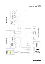
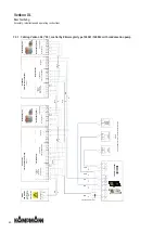
Страница 40: ...6 Climate controller type 148941 type 148942 Support bracket by others Mains 230 V 50 Hz Venkon AC electromechanical 00 Fuse by others Refer to Electrical data information table Mains 230 V AC Unit no...

Страница 41: ...rmation table Mains 230 V AC Unit no 1 Unit no 2 Valve drive s 24 V AC DC Open Close Fan junction box Mains 230 V AC Condensation pump optional Fan speed Venkon AC Electromechanical 00M Condensation a...

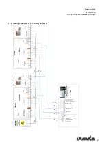
Страница 42: ...ler to the nearest KaControl unit in line with the wiring diagram The maximum bus length between the KaController and the KaControl master unit is 30 m The respective KaControl automatically becomes t...

Страница 43: ...es as low voltage and bus cables Lay all BUS cables in a linear pattern Star shaped wiring is not permitted The KaController is connected via a bus connection to the respect ive control PCB on the uni...

Страница 44: ...iption of wiring Units configured for operation with KaControl are fully wired and fitted with all electrical parts ready for connection with the exception of optional accessories The speed of the EC...

Страница 45: ...ers Refer to Electrical data information table Mains 230 V 50 Hz Venkon XL KaControl C1 Unit no 1 PCB PUR EC01 PCB SmartBoard Electrical junction box Venkon EC KaControl C1 Unit no 2 PCB PUR EC01 PCB...

Страница 46: ...2 1 2 NO COM 1 2 NO COM 1 2 3 W1 3 W2 N PE L 1 2 gn ge Mains 230 V 50 Hz KaController type 321000x Fuse by others Refer to Electrical data information table Mains 230 V AC Unit no 1 Electrical junctio...

Страница 47: ...wired throughout Check whether all lines have the necessary cross section Check whether jumpers and DIP switches have been correctly set as per the wiring diagram Water side checks Check the leak tigh...

Страница 48: ...unit is connected leak free to the on site condensation connection Check whether the waste water lines are clean and have a sufficient gradient Check whether the condensation pump has a working power...

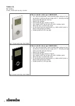
Страница 49: ...ct fan speed when operating mode selector switch is in the Manual fan position Option for external room sensor Control input for heating cooling changeover with 2 pipe systems Digital input can either...

Страница 50: ...inputs functions parametrisable e g window contact presence detector heating cooling switchover Parallel operation of 2 units is possible Fig 42 Climate controller type 196000148942 Climate controller...

Страница 51: ...inputs functions parametrisable e g window contact presence detector heating cooling switchover Parallel operation of 2 units is possible Fig 44 Climate controller type 196000148944 Climate controller...

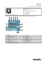
Страница 52: ...background lighting can be permanently disabled by means of a parameter setting 1 2 3 4 5 6 7 8 Fig 45 KaController with function keys type 3210002 1 Display with LED background lighting 2 ON OFF key...

Страница 53: ...hown on the display depend on the application 2 pipe 4 pipe etc and the parameters set 1 2 3 4 5 6 7 8 9 10 11 12 13 14 15 Fig 48 Display 1 Display of setpoint room temperature 2 Current time 3 Timer...

Страница 54: ...ing compon ents of the fan Wait until all parts have come to a standstill 10 2 Maintenance Schedule The sections below describe maintenance work needed for the proper and trouble free operation of the...

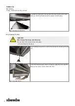
Страница 55: ...the basic unit 10 3 1 Opening the inspection flap Fig 49 Opening the latch Use an Allen key to turn the latch 90 refer to the arrow on the latch for the closing direction Fig 50 Lowering the service h...

Страница 56: ...the housing 10 3 2 Replacing the filter CAUTION Risk of injury from sharp metal housing The inner metal of the casing can have sharp edges Wear suitable protective gloves Fig 53 Turning the filter lat...

Страница 57: ...ame way as the ISO Coarse dry layer filter 10 3 3 Cleaning the condensate tray Opening the inspection flap 55 before cleaning the condensation tray Steps 1 3 are only necessary if a condensa tion pump...

Страница 58: ...itable tool to turn the M6x10 tooth locking screw from the condensa tion tray bracket Fig 60 Loosening and holding the condensa tion tray Use a suitable tool to turn the M6x10 tooth locking screw from...

Страница 59: ...ing sure that the ball studs are in serter properly into the housing IMPORTANT NOTE Fit the float switch When using a condensation pump it is essential that the float switch is replaced and fit in pla...

Страница 60: ...ed to Hydraulic connection not properly done Check flow and return and tighten if necessary Water outlet Condensate drain outlets blocked Clean condensate outlets and check for ad equate gradient Chil...

Страница 61: ...ost protection 7 A18 EEPROM error 8 A19 Offline slave in the CAN bus network 9 Tab 13 KaControl unit alarms Code Alarms tAL1 Temperature sensor in the KaController faulty tAL3 Real time clock in the K...

Страница 62: ...P010 P011 P012 P014 10 0 255 K 10 10 P014 Clip on sensor limit value temperature to activate the fan stages in cooling mode 18 0 255 C 18 P015 Function of input AI1 0 0 19 0 P016 Function of input AI2...

Страница 63: ...m fan speed 90 0 100 kOhm 90 P050 Fan setting max fan speed 100 0 100 100 P051 Fan setting min fan speed 0 0 90 0 P052 Fan setting speed limitation activated 0 0 1 0 P053 Valve actuation by pulse widt...

Страница 64: ...ancy 0 0 3 0 P094 Pre comfort timer 60 1 255 min 60 P095 Disable DIP switch settings 0 0 1 0 P096 Digital outputs controlled continuously 0 0 1 0 P097 Reading of DIP switch 0 63 P098 Actuation 0 10V s...

Страница 65: ...133 Hysteresis for outside temperature to switch between heat ing fan mode 0 0 255 K 10 0 P134 Threshold for outside temperature to switch between heat ing fan mode 0 0 50 C 0 P135 Enable virtual sens...

Страница 66: ...atic setting depending on PCB parameterisable freely programmable 1 Increment of 1 parametrisable PCBs 2 Increment of 0 5 freely programmable PCBs 0 0 2 t012 Date Time setting Year 9 0 99 t013 Date Ti...

Страница 67: ...Venkon XL Beschreibung Assembly installation and operating instructions 67 13 Certificates...

Страница 68: ...den Norm en oder normativen Dokumenten bereinstimmt to which this declaration relates is in conformity with the following standard s or other normative document s auquel se refere cette declaration es...

Страница 69: ...t date d etablissement Miejsce i data wystawienia Mfsto a datum vystavenf Kampmann GmbH Friedrich Ebert Stra e 128 130 4981 1 Lingen Ems T 49 591 7108 0 F 49 591 7108 300 E info kampmann de Seite 2 vo...

Страница 70: ...Pelec LWA kW kW kW kW dB A 6 2 1 7 10 4 0 167 67 2 9 1 5 4 8 0 085 63 12 9 4 0 21 3 0 353 70 9 4 1 7 15 7 0 281 68 Standard rating conditions for fan coil units according to regulation EU No 2016 2281...

Страница 71: ...Verordnung EU Nr 2016 2281 Standard rating conditions for fan coil units according to regulation EU No 2016 2281 Norm Pr fbedingungen f r Gebl sekonvektoren gem Verordnung EU Nr 2016 2281 27 C dry bul...

Страница 72: ...ories 19 Tab 7 Heat exchanger connection dimensions 24 Tab 8 Assignment of wire tightening clamps 32 Tab 9 Technical data for Sauermann SI30 condensation pump 32 Tab 10 Maximum electrical rating for V...

Страница 73: ......

Страница 74: ......

Страница 75: ......

Страница 76: ...www kampmanngroup com hvac products fan coils venkon xl 02 20 ENSAP Nr 1374732...

Отзывы: