background image

Version 1.08 (04/07)

Manual: CMOS Industrial Camera LOGLUX

 i5



Page 44 of 46

KAMERA WERK DRESDEN GmbH

Choosing a lens for the LOGLUX

®

 i5 CL

The camera has a standardized C mount with a flange focal length (distance from the lens mounting
flange  to  the  active  sensor  surface)  of  17.53mm,  and  an  inch-system  based  thread  1-32UN-2A
specification).
The sensor  size  calls for  CCTV lenses  which  are  at least  suitable for  2/3-inch  sensors.  In  any  case,
high-quality lenses featuring a low distortion, high image resolution, high-grade antireflection  coating,
and good contrast  ratio  should  be  used for image  processing  purposes.  Lenses  as  used  in  common
surveillance equipment are not suitable for industrial image processing applications.

Matching the flange focal length of a lens with the LOGLUX

®

 i5 CL

Production tolerances both of the lens and the optical camera system make it necessary to fine-adjust
the flange focal length using the camera adjusting feature.

Make  the  adjustment  at  full  aperture.  Set  the  focusing  ring  of  the  lens  to  „

“  ('infinity').  Point  the

camera to a well structured, sufficiently distant subject (

 2000 x focal length). Make sure  the lens  is

properly seated on the flange of the lens mount.
First loosen the three setscrews on the circumference of the lens mount flange; for  the  purpose,  use
the supplied small hexagonal wrench (wrench size 0.9) and turn the setscrews out by one full rotation
each. Then turn the lens with guide ring (!) out of the flange, or into the flange, until  the  subject  is in
optimum focus. Finally, retighten the setscrews applying not too much force.

For  more  information,  also  with  respect  to  using  zoom  lenses,  see  the  website  of  PENTAX  Europe
GmbH (

www.pentax.de

).

Frequently asked questions

Question:

What do I need the 'Advanced Features' option for?

Answer:

By means  of  this  option,  you  have  access  to  the terminal  which  is  an  integral  part  of  the
program, and to the functions in a camera firmware update. In order to avoid unintentional
activation of the above-mentioned functions, the box is normally not checked.

Question:

What do the different framebuffer display modes mean?

Answer:

The 'Grey' option shows the eight lowermost bits (MSB) of a pixel.
Option 'Blue enhanced' shows the lowermost nine bits (MSB) of a pixel and gives the black
and  white  regions  of  a  live  image  a  green  and  red  color,  respectively.  This  allows  an
underexposure or overexposure of the image to be easier detected.
The  'Pseudo  grey'  option  shows  10.5-bit  interpolated  greyscale  values  (MSB)  slightly
differing from the exact RGB greyscale values. Here, too, the black and white regions are
tinted green and red, respectively.
Please note that the two latter modes require more computer power and may, thus, result
in a lower image rate.

Question:

How can the 'Multiple integration slope mode' reasonably be configured?

Answer:

The best way is to start using an integration (exposure) time in such a way that - with the
integration  time  as  low  as  possible  -  the  details  which  are  of  interest  can  just  be  safely
discerned  in  the  dark  parts  of  the  image.  The  time  to  be  so  determined  is  the  total
integration time for the specific image. When using the 'Exposure precalculation' function in
the 'Exposure‘ configuration window of the active LuxWare profile, the user may adapt the
transmission function of the sensor by carrying out  an  approximation  to  an  exponential  or
root function. To this end, the previously determined total integration time is subdivided into
up to four partial integration times. This can also be performed manually, i.e. the user can
add up to four partial integration times to obtain the previously determined total integration
time. Reasonably, the first partial integration time should be the longest time, and the last
partial integration time should be the shortest time.

Содержание CMOS

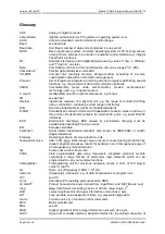
Страница 1: ...Manual CMOS Industrial Camera LOGLUX i5 CL Version 1 08 July 2004...

Страница 2: ...THE PROFILE GLOBALS MENU 16 THE USER PROFILE PARAMETERS 17 The Region of Interest profile menu 17 The Trigger profile menu 18 The Switchport profile menu 19 The Sensor profile menu 21 The Output data...

Страница 3: ...BLE 5 LIST OF REGISTER INITIAL VALUES OF FUNCTION GROUP CAMERA CONFIGURATION 32 TABLE 6 REGISTERS OF FUNCTION GROUP WORKING PARAMETERS 36 TABLE 7 REGISTERS OF FUNCTION GROUP LUT PROGRAMMING 37 Revisio...

Страница 4: ...LOGLUX i5 CL CMOS industrial camera is excluded Liability in cases of intent and gross negligence remains unaffected therefrom In any case our liability is limited to the purchase price of the unit T...

Страница 5: ...cific LUTs look up tables In the process the image data can be replaced by function values e g arithmetic operations By defining a greyscale threshold in a LUT for example the camera can be made to de...

Страница 6: ...integration or exposure time the residual potential of the sensor cell can be measured and translated into a digital numerical value By several successive integrations of the sensor cell potential wi...

Страница 7: ...bright pixels As compared with the first integration cycle slightly lower residual potentials are obtained for the dark pixels as a result of the second short integration time while the bright pixels...

Страница 8: ...cceptable for image processing For this reason the rolling curtain shutter mode should where possible only be used for imaging objects that do not move or move slowly relative to the sensor line reado...

Страница 9: ...data interfaces as used in industrial image processing In addition to the image data transmission from the camera to the host system it is also possible to control and configure the camera from the h...

Страница 10: ...for desktop PC systems for reasons of the tougher use conditions more exclusive components may occasionally have to be chosen For configuring an IPC system just contact a systems house of your choice...

Страница 11: ...apter to link the camera up with an optional triggering system e g the switching output of a light barrier in order to trigger the framegrabbing process in an event controlled mode The same plug conne...

Страница 12: ...eters Professional users have full access to all relevant sensor functions at register level by using a terminal program which is an integral part of the LOGLUX LuxWare Moreover this form of configura...

Страница 13: ...cameras connected to the respective ports the camera names are displayed the following should be noted Cameras plugged into RS 232 ports do not deliver a live image with the configuration tool Where a...

Страница 14: ...installation directory of the program The left side displays the tree structure of the parameters of the selected LOGLUX i5 CL camera and the IP hardware used framegrabber or FireWire ports The param...

Страница 15: ...ture updated immediately upon leaving the input field The camera name may have up to 32 digit positions The Baudrate option allows the communication speed to be set Once set the speed will be immediat...

Страница 16: ...the user to initialize the selected profile with one of the factory set profiles It should be noted here that all settings of the chosen profile are overwritten This option is ideal for user specific...

Страница 17: ...tance of ROI from left and width of the ROI are set in the Left and Width fields respectively The associated scroll bars can also be used for a coarse pre adjustment Only integer values may be set The...

Страница 18: ...rnal signal applied to the trigger input of the camera Triggering is effected by the rising edge of the signal CameraLink CC1 The camera is triggered by an external signal sent from the CameraLink por...

Страница 19: ...there is no controlled integration time available CameraLink CC2 A signal applied to the CameraLink port CC2 camera control 2 is assigned to the selected switchport For the generation of this signal s...

Страница 20: ...integration times to choose from To this end the user highlights under Mode the desired conversion function to be approximated and enters the value of the base of the conversion function to be approxi...

Страница 21: ...shutter modes i e synchronous shutter or rolling shutter can be selected under Shutter Under Amplification the user can set the amplification factor for the analog amplifier downstream of the sensor...

Страница 22: ...ight 1 9 The image data are subtracted from the constant 1024 which results in an inversion of the image data Subsequently the image data are shifted to the right bit by bit by n bits Zeros are insert...

Страница 23: ...d delivery the camera has no custom designed camera firmware inside If the camera has a custom designed camera firmware inside the listed additional functions can be configure by adjusting option entr...

Страница 24: ...are displayed under Lookup table contents By clicking button Save the transferred LUT can be saved as a text file in the host system PC IPC Load A LUT text file in the host system is selected to be tr...

Страница 25: ...licking the button opens the standard Windows dialog Play Macro whereupon the user may choose the desired LLM file A command sequence entered from the terminal is saved as macro Clicking the button op...

Страница 26: ...be checked to make an update or back up copy of the camera firmware The user can update the MCU firmware by clicking Update in the MCU Firmware panel By clicking Update in the FPGA Firmware panel the...

Страница 27: ...or version Under Grab image as the greyscale values of the grabbed frame can be choose between greyscale or bayer formated colour image datas Grab image as is only available with the LOGLUX i5 CL colo...

Страница 28: ...rom register ADR ADR 0 FFFFFFFF d ADR Dump register Reads register bank as from register ADR e g from the first register of a function group ADR 0 100 200 see following description of the function gro...

Страница 29: ...Address Format Description Value range Meaning Default CONFIG_SIGNATURE 00 no user access CONFIG_BAUDRATE 02 1 byte RS232 baud rate selection 12 1 115200 baud 9600 baud 1 CONFIG_EOLTYPE 03 1 byte Lin...

Страница 30: ...of the four selectable camera sensor profiles the parameters being the pixel clock rate snapshot mode trigger rate trigger mode video mode look up table used region of interest integration time modes...

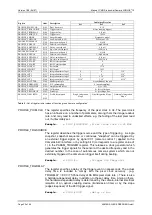
Страница 31: ...port 1 150 232 signal time in ns PROFILE_XSTART 130 1 word ROI X start position 2 x x 0 638 X coordinate in pixel PROFILE_YSTART 132 1 word ROI Y start position 0 1022 Y coordinate in pixel PROFILE_WI...

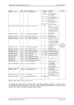
Страница 32: ...ILE_DESCRPTN 150 16F Profile description Single Integration Slope Dual Integration Slope Quadruple Integration Slope Table 5 List of register initial values of function group camera configuration PROF...

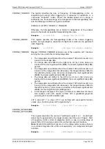
Страница 33: ...ch results in an inversion of the image data Simultaneously the image data are shifted to the right bit by bit by n bits Zeros are inserted at the most significant bits MSB the lowest significant bits...

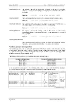
Страница 34: ...ay at 66 MHz pixel clock rate Example w 11E 100000 Switchport 1 PLength 100 us PROFILE_XSTART The register specifies the start position left of the visible sensor frame The value must represent an eve...

Страница 35: ...es the amplification factor of the analog amplifier downstream of the sensor The register value should not be changed for the following reasons The proper calibration of the camera is no longer guaran...

Страница 36: ...4 write only PARAM_TEMP0 908 1 word Temperature sensor 0 218 398 Temperature in Kelvin read only PARAM_TEMP1 90A 1 word Temperature sensor 1 218 398 Temperature in Kelvin read only Table 6 Registers...

Страница 37: ...ted to each of the possible 1024 greyscale values x of the sensor also a description of the respective LUT functions is contained in these register banks Prior to the word wise filling of the LUTx wit...

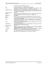
Страница 38: ...mat with trapezoidal connector screen and two or three lines of male female contacts for external PC ports e g serial RS 232 interfaces ESD Electrostatic discharge ESD caused by electrostatic charging...

Страница 39: ...terest to the user RS 232 Line standard for transmitting and receiving data via a serial interface based on the V 24 or V 28 standard SOC System on chip combination of large scale integrated function...

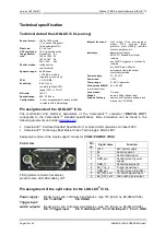
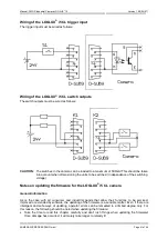
Страница 40: ...without lens Lens mount C mount Weight approx 250g without lens Scope of delivery camera with LuxWare software and manual on CD ROM Pin assignments of the LOGLUX i5 CL The mechanical and electrical pa...

Страница 41: ...of the switching voltage Notes on updating the firmware for the LOGLUX i5 CL camera General information As is the case with all consumer and industrial goods that allow their functions to be serviced...

Страница 42: ...s For this reason it is advisable to check if a new version of the LOGLUX LuxWare software is available when for instance the MCU firmware is updated On the other hand an extension of the LOGLUX LuxWa...

Страница 43: ...the contents of file LOGLUXi5CL_xxx bin with xxx standing for the current version in the user specific source directory must be transferred to the camera Select the Firmware profile menu Activate the...

Страница 44: ...means of this option you have access to the terminal which is an integral part of the program and to the functions in a camera firmware update In order to avoid unintentional activation of the above m...

Страница 45: ...hich are supported by the LuxWare configuration tool Other CameraLink framegrabbers may be used to configure the LOGLUX i5 CL camera by means of the INI file of the LuxWare configuration tool see Addi...

Страница 46: ...COM port of the LOGLUX i5 CL camera For a very safe and very fast communication between the host system PC IPC and camera the serial COM port of the LOGLUX i5 CL camera is recommended to be used Howev...

Отзывы: