Manual: CMOS Industrial Camera LOGLUX
i5
Version 1.08 (04/07)
KAMERA WERK DRESDEN GmbH
Page 33 of 46
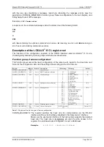
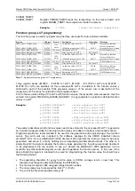
PROFILE_TRGRATE
The register specifies the rate, or frequency, of framegrabbing (in Hz, or
snapshots per second) after triggering for a sequence of snapshots or a
continuous "snapshot" (video). Where the readout speed of an image is
sufficiently low, the actual image rate corresponds to the framegrabbing rate,
with the following condition having to be satisfied:
PIXELCLK / (WIDTH * HEIGHT) < TRGRATE
Otherwise, the framegrabbing rate is limited in dependence of the readout
speed to the maximum possible framegrabbing rate value.
Example:
w $108 #30
;Image rate is 30 Hz
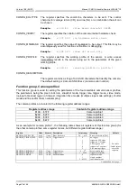
PROFILE_SMODE
This register specifies the framegrabbing mode of the camera triggering
system. A single snapshot, sequence of snapshots or video can be generated
upon triggering.
Example:
w $10A #1
;Trigger for single snapshot
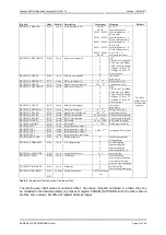
PROFILE_TMMODE
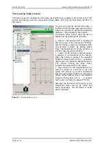
Register PROFILE_TMMODE activates one of the available LUT functions
serving the link-up with the incoming image data:
•
The image data are subtracted from the constant 1024 which results in an
inversion of the image data.
•
The image data are shifted to the right bit by bit (by n bits). Zeros are
inserted at the
most significant bits
(MSB), the
lowest significant bits
(LSB)
get lost.
•
The image data are subtracted from the constant 1024 which results in an
inversion of the image data. Simultaneously, the image data are shifted to
the right bit by bit (by n bits). Zeros are inserted at the
most significant bits
(MSB), the
lowest significant bits
(LSB) get lost.
•
The image data are shifted to the left bit by bit (by n bits). Zeros are
inserted at the
lowest significant bits
(MSB), the
most significant bits
(LSB)
get lost.
•
The image data are subtracted from the constant 1024 which results in an
inversion of the image data. Simultaneously, the image data are shifted to
the left bit by bit (by n bits). Zeros are inserted at the
lowest significant bits
(MSB), the
most significant bits
(LSB) get lost.
•
A test image is displayed. The region of interest is subdivided into fixed-
size squares, and each square is filled with a graduated greyscale
extending from top left to bottom right.
LUT’s ‚User LUT 1‘ to ‚User LUT 3‘ can be filled with user-specific function
values (see „Function group ‚LUT programming‘“).
Example:
w $10C $0601
;User LUT 1 is selected
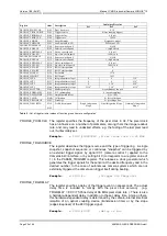
PROFILE_SW0SOURCE
PROFILE_SW1SOURCE
This register describes the source of switchport signal 0 or 1. A switchport
signal may be generated by the trigger module upon the event ‚Trigger‘, ‚Start
of Integration‘ (SOI) or ‚End of Integration‘ (EOI), or due to a rising slope of
signal CC2 or CC3 (camera control 2/3) via the CameraLink
interface.
Note:
Events SOI and EOI will not occur in the
rolling shutter
mode as there is
no controlled integration time and, consequentially, no configured switchport
activities.
Example:
w $10E #6
;Switchport 0 upon event Reg.

