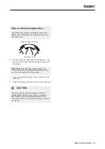
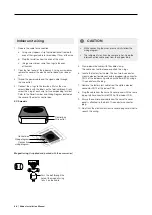
background image

22

  |  Kaden Installation Manual

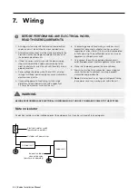
7.  Wiring

      BEFORE PERFORMING ANY ELECTRICAL WORK,  

READ THESE REQUIREMENTS

1.  All wiring must comply with local and national electrical 

codes, and must be installed by a licensed electrician.

2.  All electrical connections must be made according to the 

Electrical Connection Diagram located on the panels of 
the indoor and outdoor units.

3.  If there is a serious safety issue with the power supply, 

stop work immediately. Explain your reasoning to the 
client, and refuse to install the unit until the safety issue is 
properly resolved.

4.  Power voltage should be within 90 and100% of rated 

voltage. Insufficient power supply can cause malfunction, 
electrical shock, or fire.

5.  If connecting power to fixed wiring, install a surge 

protector and main power switch with a capacity of  
1.5 times the maximum current of the unit.

6.  If connecting power to fixed wiring, a switch or circuit 

breaker that disconnects all poles and has a contact 
separation of at least 3mm (1/8 in) must be incorporated 
in the fixed wiring. The qualified technician must use an 
approved circuit breaker or switch.

7.  Only connect the unit to an individual branch circuit 

outlet. 

Do not

 connect another appliance to that outlet.

8.  Make sure to properly ground the air conditioner.

9.  Every wire must be firmly connected. Loose wiring can 

cause the terminal to overheat, resulting in product 
malfunction and possible fire.

10. 

Do not

 let wires touch or rest against refrigerant tubing, 

the compressor, or any moving parts within the unit. 
 

 WARNING

BEFORE PERFORMING ANY ELECTRICAL OR WIRING WORK, TURN OFF THE MAINS POWER TO THE SYSTEM.

Note on isolator

An electrical isolator must be installed adjacent the outdoor unit so it can be switched off in an emergency.


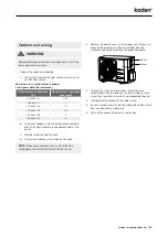
Outdoor unit

Indoor & outdoor 

connective wires 

(purchased separately)

Indoor unit

Electrical isolator switch 

(purchased separately)

Outdoor unit power wires

Содержание KCS Series

Страница 1: ...Installation Manual CASSETTE AIR CONDITIONER KCS Series KCS24 KCS36 KCS42 KCS48...

Страница 2: ......

Страница 3: ...n pipe length 18 Connection instructions Refrigerant piping 19 Note on minimum bend radius 21 7 Wiring 22 Note on isolator 22 Outdoor unit wiring 23 Indoor unit wiring 24 Power specifications 25 8 Lea...

Страница 4: ...ion is not done properly the unit may drop and cause serious injury and damage Only fully qualified licensed personnel should install service or carry out maintenance to this air conditioning unit All...

Страница 5: ...cables tightly and clamp them securely to prevent external forces from damaging the terminal Improper electrical connections can overheat and cause fire and may also cause shock All electrical connec...

Страница 6: ...unit in a location that may be exposed to combustible gas leaks If combustible gas accumulates around the unit it may cause fire Do not turn on the power until all work has been completed When moving...

Страница 7: ...l Name of accessories Qty pc Shape Name of accessories Qty pc Shape Owners Installation Remote Controller Manuals 3 Drain joint 1 Soundproof insulation sheath 1 Seal ring 1 Soundproof insulation sheat...

Страница 8: ...Installation summary Install the indoor unit Install the drainpipe Install the outdoor unit Pressure test and evacuation Connect the wires Connect the refrigerant pipes Install the front panel Perfor...

Страница 9: ...ghtly different in different areas Note on illustrations Illustrations in this manual are for explanatory purposes The actual shape of your indoor unit may be slightly different 1 Air outlet 2 Air inl...

Страница 10: ...ll the entire room There is no direct radiation from heaters DO NOT install unit in the following locations Areas with oil drilling or fracking Coastal areas with high salt content in the air Areas wi...

Страница 11: ...t 1m of space on all sides The cut hole size should be 4cm larger than the body size Be sure to mark the areas where ceiling hook holes will be drilled KCS24 48 models ceiling hole size Refrigerant pi...

Страница 12: ...on bolts into the unit s hanging holes Fasten them using the included washers and nuts NOTE The bottom of the unit should be 10 18mm higher than the ceiling board Generally L indicated in the followin...

Страница 13: ...water drainage 3 Place the protective wall cuff in the hole This protects the edges of the hole and will help seal it when you finish the installation process CAUTION When drilling the wall hole make...

Страница 14: ...etween the unit and the lift pipe must be less than 30cm Incorrect installation could cause water to flow back into the unit and flood To prevent air bubbles keep the drain hose level or slightly slop...

Страница 15: ...l The minimum height must be 45cm above the base pad DO NOT install unit in the following locations Near an obstacle that will block air inlets and outlets Near a public street crowded areas or where...

Страница 16: ...ng 1 Insert the drain joint into the hole in the base pan of the unit The drain joint will click in place 2 Connect a drain hose extension not included to the drain joint to redirect water from the un...

Страница 17: ...946mm x 810mm x 410mm 673mm 403mm 952mm x 1333mm x 415mm 634mm 404mm Rows of series installation The relationships between H A and L are as follows L A L H L 1 2H 25 cm or more 1 2H L H 30 cm or more...

Страница 18: ...CAUTION Oil traps If the indoor unit is installed higher than the outdoor unit If oil flows back into the outdoor unit s compressor this might cause liquid compression or deterioration of oil return...

Страница 19: ...urrs Burrs can affect the air tight seal of refrigerant piping connection They must be completely removed 1 Hold the pipe at a downward angle to prevent burrs from falling into the pipe 2 Using a ream...

Страница 20: ...w pressure pipe then the high pressure pipe 1 When connecting the flare nuts apply a thin coat of refrigeration oil to the flared ends of the pipes 2 Align the centre of the two pipes that you will co...

Страница 21: ...le with other wires While bundling these items together do not intertwine or cross the signal cable with any other wiring 7 Thread this pipeline through the wall and connect it to the outdoor unit 8 I...

Страница 22: ...connecting power to fixed wiring a switch or circuit breaker that disconnects all poles and has a contact separation of at least 3mm 1 8 in must be incorporated in the fixed wiring The qualified techn...

Страница 23: ...pproximately 15cm of wire c Strip the insulation from the ends d Using a wire crimper crimp u lugs on the ends NOTE When connecting the wires strictly follow the wiring diagram found inside the electr...

Страница 24: ...accessories CAUTION While connecting the wires please strictly follow the wiring diagram The refrigerant circuit can become very hot Keep the interconnection cable away from the copper tube 5 Clamp d...

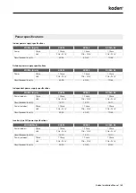
Страница 25: ...ependent power supply specifications MODEL Btu h KCS24 KCS36 KCS42 48 Power indoor Phase 1 Phase 1 Phase 1 Phase Volt 208 240V 208 240V 208 240V Circuit breaker fuse A 15 10 15 10 15 10 Power outdoor...

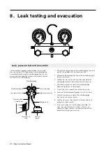
Страница 26: ...a leak detector and bubble solution Safely release the test pressure 4 Open the low pressure side of the manifold gauge Keep the high pressure side closed 5 Turn on the vacuum pump to evacuate the sys...

Страница 27: ...valve by turning the wrench in a 1 4 counter clockwise turn Listen for gas to exit the system then close the valve after 5 seconds 2 Watch the pressure gauge for one minute to make sure that there is...

Страница 28: ...ooks of the indoor unit Tighten the panel hook screws evenly at the four corners NOTE Tighten the screws until the thickness of the sponge between the main body and the panel reduces to 4 6mm The edge...

Страница 29: ...d drainpipe are not affected by this adjustment CAUTION Failure to tighten screws can cause water leakage CAUTION If the unit is not hung correctly and a gap exists the unit s height must be adjusted...

Страница 30: ...c Double check to see if the room temperature is being registered correctly d Ensure the indicators on the remote control and the display panel on the indoor unit work properly e Ensure the manual but...

Страница 31: ...door unit EEPROM parameter error 6 times F5 Outdoor fan speed has been out of control 1 times P0 IPM malfunction or IGBT over strong current protection 2 times P1 Over voltage or over low voltage prot...

Страница 32: ...kadenair com au...

Отзывы: