background image

Page 42

                                                     Operating Instructions Powador-proLOG_EN

S e c t i o n   9   ·  

C o n f i g u r a t i o n   E x a m p l e

9  Confi guration Example

9.1 Analogue 

channels

9.1.1 Voltage 

input

The rule for converting the measured computation value to a 
physical value is as follows:

Legend:

[MW]: current measured value at the channel input in [V].
[Measuring scale fi nal value]:   for a voltage input  of 10 
volts.

Example 1:
A sensor is to be connected to an analogue channel using 
a sensor constant of 10 V = 1500 W/m². The measurement 
range fi nal value of the input is 10 V.
The slope is calculated as follows:

If the channel does not show an offset during calibration, you 
can use 0 for the offset. Assuming the channel has an offset 
of +15 W/m² (for example) during calibration, set the channel 
as follows:

Example 2:
A PT100 is to be connected to a channel using a voltage trans-
former. The voltage transformer supplies an output voltage of 
10 V at +100°C and an output voltage of 0 V at –50°C. This 
results in a physical measurement range fi nal value of 150°C.
The slope is calculated as follows:

Since the temperature is to be measured down to -50 °C, the 
result is an offset of:

Physical full-scale value

Channel full-scale value

Physical value

 ] = [ 

IV

 ] × [ 

Gradient

 ] + [ 

Offset

 ]

=  

Instantaneous channel value

IV

 ]

Gradient

 ]  =

=  

Physical measured value

Offset

 ]

 Physical measured value

=  

 ∑ 

pulses

Meter constant

9.1.2 Current 

input

The rule for converting the measured computation value to a 
physical value is as follows:

Legend:
[MW]: Current measured value at the channel input  in [mV].
[Measuring scale fi nal value]:    for a current input of 20 mA.

9.2  Digital inputs

The following equation is used to convert to a physical quan-
tity:

Example:    A counter provides 6000 pulses/kWh and is to be 
connected to a digital input. This counter constant is directly 
entered as a value in the Pulse constant (pulses/kWh)] fi eld, 
which means that the online display shows the values as 
energy [kWh]. To display the current power, you have to enter 
a value (e.g. 60) in the Interval for current power (s)] fi eld. 
This means that the pulses are added up over a period of 60 
seconds and converted to an average power for this interval 
period.

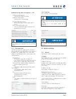
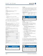
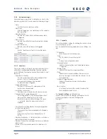
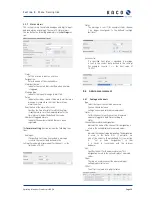
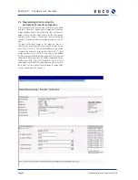
9.3  Alarm criterion

An example should help you to achieve simple and effective 
system monitoring with the unit.

Example:
A photovoltaic system is equipped with a solar sensor for 
measuring irradiance in the module level and a generation 
counter with pulse output. These quantities are to be used to 
defi ne limits for reporting a defect in the system by means of 
a “malfunction call”.

Physical full-scale value

Channel full-scale value

Physical value

 ] = [ 

IV

 ] × [ 

Gradient

 ] + [ 

Offset

 ]

=  

Instantaneous channel value

IV

 ]

Gradient

 ]  =

=  

Physical measured value

Offset

 ]

Gradient

 ]   =  

=  

 1500 

W/m²

10

150

²

/

15

m

W

Offset


Gradient

 ]   =  

=  

 150 

°C

10

15

=  

Offset

 ]    -50 

°C

Содержание Powador-proLOG

Страница 1: ...Powador proLOG Operating instructions...

Страница 2: ...6 3 Notes on installation and operation 7 3 1 Intended use 7 3 2 Factory warranty and liability 7 3 3 Service 7 4 Technical Data 8 5 Installation 10 5 1 Determining the installation location 10 5 2 In...

Страница 3: ...rter details 33 8 3 Status 33 8 3 1 System messages 33 8 3 2 Inverters 34 8 4 Con guration 34 8 4 1 System data 34 8 4 2 Standard contact 35 8 4 3 Date Time 35 8 5 Admin monitoring 35 8 5 1 Network 35...

Страница 4: ...ctions High voltage Read the manual 1 4 CE marking The CE marking is used to document that the Powador pro LOG data logger shown on the name plate ful ls the funda mental requirements of the following...

Страница 5: ...Transportation The Powador proLOG is subjected to extensive testing and inspections at our test facility Only by doing so can we ensure the high quality of our products Our data loggers leave our fact...

Страница 6: ...equipment Unauthorised modi cations to the units or repair attempts In uence of foreign objects or force majeure lightning overvoltage severe weather re Failure to observe the relevant safety regulat...

Страница 7: ...5 to 24 5 23 5 to 24 5 Max current consumption for sensors depending on modem variant Ethernet DSL mA 230 230 230 ISDN modem mA 230 Analogue modem mA 190 190 GSM GPRS modem mA 160 Mechanical data Disp...

Страница 8: ...tal inputs Number of 1 1 4 S0 pulse input DC V Low 0 to 7 High 9 to 24 Low 0 to 7 High 9 to 24 Low 0 to 7 High 9 to 24 Powered exclusively by the unit s internal power supply Can be con gured as a sta...

Страница 9: ...drill holes The distance between the screws on the mounting bracket and the wall should be approx 3 mm Hang the Powador proLOG on the screw heads and then pull down Now secure the Powador proLOG with...

Страница 10: ...installation process is shown in the two images below a Insert the patch cable RS485 into the ferrite clip and close it b Connect the patch cable to the Powador go port on the Powador proLOG and attac...

Страница 11: ...stalling the network cable please note that a crosso ver cable included in the scope of delivery is required for direct communication between the Powador proLOG unit and a PC However if you intend to...

Страница 12: ...roLOG directly to a PC you must use a crossover cable included in the scope of delivery If you want to connect it to a switch or hub you require a patch cable NOTE The designations for A and B vary be...

Страница 13: ...nverters is restricted to a maximum of ten units as each one occupies three addresses The Powador proLOG S is limited to a maximum output of 50 kWp NOTE Consulttherelevantinvertermanualformoreinformat...

Страница 14: ...ser ATTENTION The output is designed as an optocoupler output N O contact and must therefore be connected to an external voltage supply if necessary The maximum load is 50 mA NOTE The analogue inputs...

Страница 15: ...ungs schutzschalter B6 A Powador proLOG M 1x AI 1x DI 1x DO Powador proLOG XL 4x AI 4x DI 1x DO Analoge Eing nge AI 0 10 V DC PT1000 Digitale Eing nge DI Optisch getrennt Low 0 7 V DC High 9 24 V DC D...

Страница 16: ...wador proLOG receives the corresponding signal via the radio ripple control receiver The Powador pro LOG then forwards the information to all connected inverters as a command via the RS485 interface A...

Страница 17: ...ected to the 24 V external terminal strip Reset Use the reset button to restart the Powador proLOG 5 6 Pin assignment 5 7 Jumper switch M XL only The Powador proLOG M XL has three jumper switches loca...

Страница 18: ...can download the application form from our wesite www kaco newenergy de 6 3 Using the Powador proLOG without Powador web 1 Once you have successfully connected to the Powador proLOG you should con gur...

Страница 19: ...nstallation You can also query current measured values and stored energy yields while the unit is operating Navigating through the display menu EXIT Cancel input Go back one menu level DOWN Select a m...

Страница 20: ...s System Energy of DI Current power Yield today Yield yesterday Monthly yield Annual yield Total yield Alarms Faults Communication System error Current subnet mask Current gateway Language Deutsch Eng...

Страница 21: ...by the BOOTP DHCP server Gateway The gateway that is used when one was not assigned by the BOOTP DHCP server Modem ISDN GSM Local IP address The IP address that the Powador proLOG has in the WAN Remot...

Страница 22: ...ation To ensure optimum operation of the Powador proLOG we rec ommend that you take advantage of the agreement that we offer The costs for this agreement are passed on one to one The alternatively use...

Страница 23: ...e SIM card forward 3 Connect the antenna The antenna connection is located in the connection area next to the 230 V grid connection Connect the included antenna here 4 Start the Powador proLOG On deli...

Страница 24: ...k Ethernet The Powador proLOG and the computer must be connected to the same network The IP addresses and the netmask for the Powador proLOG or computer must be in the same address space As soon as th...

Страница 25: ...e connected to your PC and installed Access the Network Connections menu item by selecting Start Settings Control Panel Now select the New Connection Wizard 2 Step Select the New Connection Wizard and...

Страница 26: ...ame and the password Enter admin for both the user name and the pass word Section 7 Establishing a Connection proLOG NOTE Check boxes 2 Make this the default Internet connec tion and 3 Turn on Interne...

Страница 27: ...r The standard address is http 192 168 200 1 Con rm this address to access the start page for the Powador proLOG Section 7 Establishing a Connection Connect to proLOG proLOG Properties NOTE From now o...

Страница 28: ...cation The Powador web Internet portal must be requested sepa rately Set up and usage are subject to various costs The application form is available for download from the KACO new energy website To av...

Страница 29: ...ced users The following menu items show the start page 8 1 General 8 2 Online values 8 3 Status 8 4 Con guration The following additional menu items can be accessed by the administrator 8 5 Admin moni...

Страница 30: ...nt sensors Inverters Standard con tact Contact addresses Digital Channels Powador Argus Date time Switching output Extension Modules Inverter overview System messages Current sensors Inverter details...

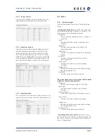
Страница 31: ...s calculated in the Admin measurement Energy of digital channels section This section lists the measured values for each digital input Current power The pulse constant is used to convert counter pulse...

Страница 32: ...me that was de ned in Formula Criterion is shown here Status Indicates whether the criterion is de ned as active or inactive Upper limit This shows the current upper limit value for the monitoring cri...

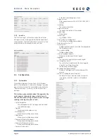
Страница 33: ...Used when calculating alarm criteria Degree of ef ciency of modules Used when calculating alarm criteria Degree of ef ciency of inverters Used when calculating alarm criteria Number of sub systems Use...

Страница 34: ...on by fax the fax number may not contain formatting characters E mail E mail address for alarm noti cation by e mail max 40 characters 8 4 3 Date Time This is where you set the time and date 8 5 Admin...

Страница 35: ...u make settings for sending e mail messages The SMTP server outbox section includes settings for IP address and e mail address This information is needed for the Powador proLOG to send e mail messages...

Страница 36: ...ddresses section These contacts are in addition to the standard contact and are alerted in the event of a fault Fill in the elds in the same way you did for the standard contact address 8 5 3 Switchin...

Страница 37: ...deviation alarm type The characteristic curves of the inverters must remain within this range The alarm is activated when the upper or lower limit is exceeded Time hour for checking whether the invert...

Страница 38: ...ata de ned in the settings for example measurement for channel 1 the limit value of 8 0 V Status The message is sent if for example status channel 1 no longer corresponds to the de ned low high fault...

Страница 39: ...3 Extension modules You can use up to eight add on modules to increase the number of inputs on the Powador proLOG In this case the Powador proLOG communicates with the extension modules over the loca...

Страница 40: ...m to activate the KACO power control function active power control and con gure the relevant Powador proLOG as a master or slave b Control You can use the Control menu item to con gure a wide variety...

Страница 41: ...ue Offset Physical measured value pulses Meter constant 9 1 2 Current input The rule for converting the measured computation value to a physical value is as follows Legend MW Current measured value at...

Страница 42: ...0 9 1 0 1 1 Gmod W m P ac kW 0 100 200 300 400 500 600 700 800 900 1000 1100 Pac Gmod eta mod eta WR area 0 4 0 2 0 0 2 0 4 0 6 0 8 1 0 1 2 1 4 Gmod W m P ac kW 0 100 200 300 400 500 600 700 800 900...

Страница 43: ...ulated with each recording interval or once a day The code for the daily energy of the respective inverter is entered in the x and y elds in the formula settings section here EWR_3 EWR_4 The reason th...

Страница 44: ...ector temperature T_K0 C Collector temperature part 1 T_K1 C Direct current I_DC_0 A Direct current of sub system 1 I_DC_1 A Direct current of sub system 2 I_DC_2 A Direct current of sub system 3 I_DC...

Страница 45: ...for CF cards a PC or laptop and the new software which you can obtain via the monitoring service Section 10 Update DANGER Before starting the update make sure to disconnect the power plug for the data...

Страница 46: ...aily les on the Powador proLOG Open the le anlage ini which you can nd in path ISTCONF ANLAGE and enter the serial number of your data logger ACTION Insert the CF card again with the KACO new energy l...

Страница 47: ...indow 4 Now set up a connection to the Powador proLOG by pressing the button FTP and then the button New connection Default settings IP address 192 168 100 50 User name admin Password admin ACTION 5 I...

Страница 48: ...Neckarsulm Germany Phone 49 7132 3818 0 Fax 49 7132 3818 703 info kaco newenergy de www kaco newenergy de The text and gures re ect the current technical state at the time of printing Subject to tech...

Отзывы: