10.4
Other grid-supporting functions that are effective in the case of active power
10.4.1 Permanent power gradient limitation
The maximum active and apparent power to be installed for a generation plant is agreed between the grid op-
erator and plant operator. The device capacity of a plant can be set to the exact agreed value using the S
lim
and
P
lim
settings. To ensure that the load on the devices in the plant is uniform, we recommend distributing the per-
formance reduction evenly across all devices.
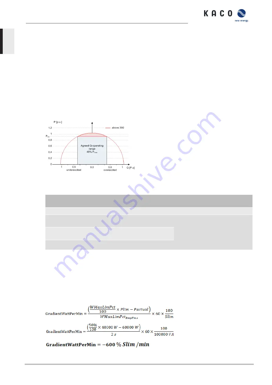
Some grid connection rules insist that the agreed reactive power be supplied from every operating point of the
plant without a reduction in the actual active power. Considering the fact that all KACO TL3 inverters have a
semi-circular P-Q operating range, a reduction in the active power is, however, required during operation at
maximum active power because an apparent power reserve is not available. By adjusting P
lim
, the maximum
active power can be restricted in order to establish an apparent power reserve and ensure that the agreed re-
active power can be delivered from any active power operating point. The graphic [See figure 58 [
shows the appropriate P-Q operating range with a required example active power of 48% of the maximum ap-
parent power of the plant or 43% of the maximum active power of the plant.
Fig. 58:
P-Q operating range with limited active power (Qmax=Smax≠Pmax) for PV inverters
The power reduction parameters can be adjusted in SunSpec model DID123. During this process, you should
also check whether internal and/or external power reduction is active.
Internal power limitation
Parameters for external power
limitation
Parameters for power limitation
Status = active
Status = active
Parameters in SunSpec model 123:
Maximum apparent power S
lim
=
100000 VA
“WMaxLimPct” = 50% P
lim
(
approx. 40000
W
)
“WMaxLimPct_RvrtTms” =
60 s
“WMacLimPct_RmpTms” =
2 s
“WMaxLim_Ena” =
1
Maximum active power P
lim
=
80% (approx. 80000 W)
AC fallback active power Pfb =
75%
P
lim
(approx. 60000 W)
PT1 settling time = 1 s
Tab. 6:
Sample parameters for power limitation
If the ramp time
“WMaxLimPct_RvrtTms”
in the SunSpec model is specified as 0 s, then the internal output
gradient is used. Otherwise, the set value will be used.
Irrespective of the communication protocol used, the settling time
“WMaxLim_Ena”
is used in order to trans-
fer the new power value. Otherwise, the internally configured value will be used.
The additional ramp time “
WMaxLimPct_RmpTms”
specifies the jump time from a power value to the new
power value.
The following formulae are used to calculate the gradient S
lim/min
:
10 | Specifications
Manual
KACO blueplanet 3.0 TL3 KACO blueplanet 4.0 TL3 KACO blueplanet 5.0 TL3 KACO blueplanet 6.5 TL3 KACO
blueplanet 7.5 TL3 KACO blueplanet 8.6 TL3 KACO blueplanet 9.0 TL3 KACO blueplanet 10.0 TL3
Page 68
EN


