background image


KACO blueplanet 3.0 NX3 M2 KACO blueplanet 5.0 NX3 M2 KACO blueplanet 8.0 NX3 M2 KACO blueplanet 10.0 NX3 M2


KACO blueplanet 15.0 NX3 M2 KACO blueplanet 20.0 NX3  M2

                                                                                                                                                                                                                                Page 30  


Note:

 The connection is established 

exclusively via the hotspot until 

step 6

This is how long your mobile end device 

must be kept near the communication 

unit. 


4. Confirm the WLAN network of the 

communication unit by tapping the 

B…


number displayed. 


Note:

 After a short time you will have 

options in <Network Configuration>. 

Option 1

- Connect the communication unit 

to the local WLAN network. 

Option 2

 –Use the existing hotspot: 

Now 

follow the instructions in Chapter 9.5.2 on 

page 31 


5.


Select the customer’s WLAN network. 

The customer needs to enter the password 

and press the <Confirm> button. 


Note:

 If the connection fails, the 

communication unit is not in range of the 

customer’s router. You can improve the 

signal quality between the communication 

unit and the router by interposing a 

repeater

. However, this must also be 

connected to the same network. 


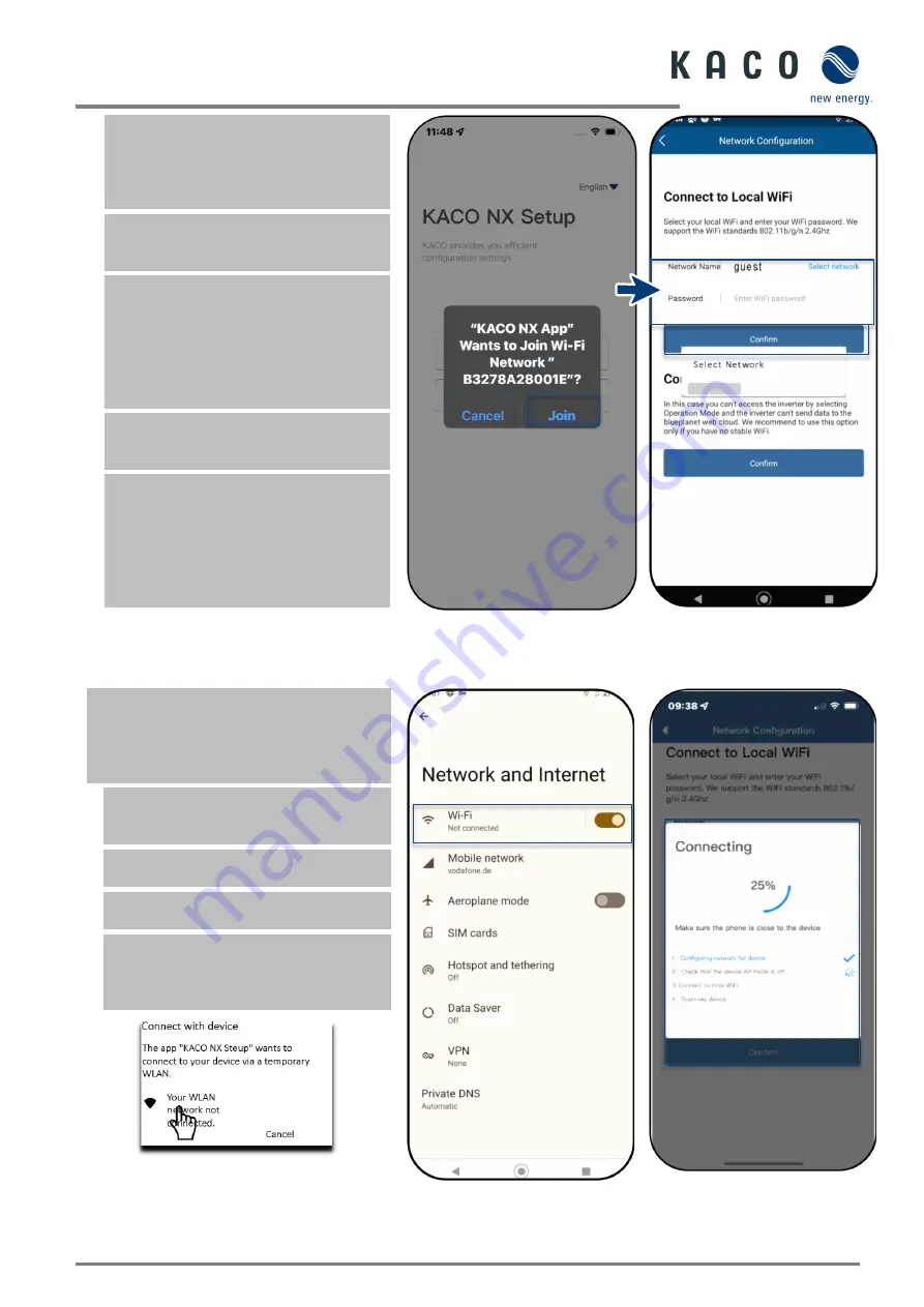
Fig. 44.


Access to the 

communication unit with a 

mobile end device 

Fig. 45.


Enter the access data for the 

customer’s WLAN network 

Note:

 If the connection is successful, your 

communication unit will be connected to the 

customer’s WLAN network. Your mobile end 

device now also needs to be connected to the 

customer’s WLAN network. 


6. In <Settings> on the mobile end device, 

you now need to establish a connection 

with the customer's WLAN network.  


Note: 

The password is pre-filled if a 

connection already exists. 


7. Note the checklist and status. Process 

takes up to 5 minutes. 


»

 Your communication unit and your 

mobile end device are now on the same 

customer WLAN network. A successful 

connection is displayed in a new window. 


Fig. 46.


Connect the inverter to the customer’s 

WLAN 

Fig. 47.


Connect the mobile end 

device to the customer’s WLAN


Fig. 48.


The connection to the 

customer’s WLAN network is 

established


Содержание blueplanet 3.0 NX3 M2

Страница 1: ...ly by KACO new energy GmbH Manual English translation of German original MNL_blueplanet 25 0 33 0 NX3_de_20 Authorised electrician Important safety instructions Android APP iOS APP Installation video...

Страница 2: ...k of identification does not mean that a product or designation logo is free of trademarks Software This device contains open source software developed by third parties and in some cases licensed unde...

Страница 3: ...terfaces 21 7 8 Connecting the Smart Meter for dynamic feed23 8 Commissioning 24 8 1 Requirements 24 8 2 Preconditions relating to standards 24 9 Configuration and operation 25 9 1 Precondition 25 9 2...

Страница 4: ...al can be downloaded from www kaco newenergy com English translation of German original This document has been produced in several languages The German version is the original version All other langua...

Страница 5: ...ation and notes Information that is important for a specific topic or objective but that is not safety relevant 1 3 4 Symbols for instructions Prerequisite for use 1 Perform next step 2 Additional act...

Страница 6: ...2 KACO blueplanet 20 0 NX3 M2 1 5 Marking You will find the name plate with the following data for service and other requirements specific to installation on the right side panel of the product Produc...

Страница 7: ...the live device Do not touch the electrical connections Remove all jewellery from your wrists and fingers Ensure that the testing equipment is in safe operating condition Modifications to the surroun...

Страница 8: ...evice RCMU Residual Current Monitoring Unit Overvoltage conductor varistor to protect the power semiconductors from high energy transients on the grid and generator sides System for monitoring the dev...

Страница 9: ...with two inverters Key Definition information on the connection PV generator The PV generator converts the radiant energy of sunlight into electrical energy Inverter The PV generator is connected to t...

Страница 10: ...3 15 2 A 220V 3 14 5 A 230V 3 13 9 A 240V 3 22 8 A 220V 3 21 8 A 230V 3 20 9 A 240V 3 30 3 A 220V 3 29 A 230V 3 27 8 A 240V Max continuous current 4 8 A 8 0 A 12 8 A 16 0 A 24 0 A 31 9 A Contribution...

Страница 11: ...ation unit RS485 Communication WLAN SunSpec Modbus TCP IP SunSpec Modbus RTU KACO Legacy Protocol Radio technology WLAN 802 11 b g n Frequency spectrum 2 412 MHz 2 472 MHz Antenna gain 2 dBi Potential...

Страница 12: ...H Check the equipment included Inspect the device thoroughly Immediately notify the shipping company in case of the following o Damage to the packaging that indicates that the device may have been da...

Страница 13: ...ll be billed to the customer Installation space As dry as possible climate controlled The waste heat must be dissipated away from the device Unobstructed air circulation When installing the device in...

Страница 14: ...packaging 2 Device 4 Lifting position The device has been transported to the installation site 1 Loosen packaging tape from cardboard box 2 Open the packaging box at the top 3 Remove installation mate...

Страница 15: ...on Ensure that no foreign bodies prevent heat dissipation following device installation Key 1 Drill three holes 10mm depth 70mm 5 Screw for securing purposes 2 Arrow on wall mount A Minimum clearance...

Страница 16: ...s when lifting and lowering the device Lifting and installing the device The mount has been installed 1 Lift the device using the recesses Observe the centre of gravity 2 Fit the device onto the mount...

Страница 17: ...s been switched off and disconnected Coming into contact with the lines and or terminals busbars in the device can cause serious injury or death Do not open the device The device must be mounted in a...

Страница 18: ...on provided by customer Max 32 A at 16 mm Tightening torque 2 0 Nm Communication Recommended RS485 bus cable Li2YCYv twisted pair black for laying cable outside and in the ground 2 x 2 x 0 5 mm Li2YCY...

Страница 19: ...minimum clearance of 20 cm Never lay cables over semiconductors cooling bodies Excessive bending force may negatively impact the protection rating Lay the cables with a bending radius of at least 4 t...

Страница 20: ...disconnect DC connectors under load Legend 1 Wire for DC connection 5 Cable fitting 2 Spring 6 Contact plug 3 Insert 7 Coupling 4 Sleeve You have completed assembly NOTE Before proceeding with the iso...

Страница 21: ...tor If stable voltages can be measured there is a ground fault in the DC generator or its wiring The ratio between the measured voltages gives an indication as to the location of this error 3 Rectify...

Страница 22: ...mum permissible power is 1 1x 15 kW 16 5 kW and each MPPT current is limited to 20 A since one MPPT is rated for 32 A and the other for 20 A Fig 24 Recommended connection in parallel operation for blu...

Страница 23: ...onnecting the PV generator The DC plug connector has to be configured and PV generator checked to ensure there is no ground fault NOTE Note the different current carrying capacity of PV1 and PV2 depen...

Страница 24: ...can be damaged beyond repair by electrostatic discharge Earth yourself before touching the components NOTE Damage to the communication unit due to rotation of the stick housing When the communication...

Страница 25: ...through configured RJ45 connector with integrated 120 Ohm terminating resistor See Fig 29 Follow the connection diagrams in the associated application note Dynamic feedin limit and blueplanet web publ...

Страница 26: ...ion with a maximum installation length across all inverters of 1000 m The individual and control connected must be measured in accordance with EMC requirements EN 62920 if the length of the cable atta...

Страница 27: ...lator switch 0 1 The device begins operation During initial start up Follow the instructions in the associated application note Installing and using the app NOTE For initial start up of the device the...

Страница 28: ...ication unit Step 2 Configuring the communication unit and inverter We recommend the following steps for the initial start up Configuration communication unit Set up time zone See Chapter 9 7 1 on Pag...

Страница 29: ...word for the inverter can be requested from KACO Service https kaco newenergy com de service kundendienst NOTE Frequency band Before configuring the network make sure that the WLAN router supports the...

Страница 30: ...p via hotspot with APP connection to the inverter with communication unit Fig 38 Set up communication unit via mobile end device hotspot Option 2 Set up via local network Fig 39 Set up communication u...

Страница 31: ...ication unit is in AP mode The communication unit forms a hot spot for a direct communication connection Reasons for this could be The communication unit has not yet been integrated into a local netwo...

Страница 32: ...unit Max distance from the scan frame shown in the scan window See Fig 43 The connection to the hotspot WLAN is established B Fig 42 Select Commissioning Fig 43 Scan QR code on communication unit Comm...

Страница 33: ...You can improve the signal quality between the communication unit and the router by interposing a repeater However this must also be connected to the same network Fig 44 Access to the communication u...

Страница 34: ...unctional status The communication unit is registered on the customer s WLAN network Fig 49 Status when connection is successful Fig 50 Connection established blue LED flashes 9 6 2 Connecting the dev...

Страница 35: ...ng or exiting initial start up the serial number based password is required to set further parameters See Chapter 9 11 6 on page 36 Fig 53 Menu of the communication unit 9 7 1 Setting the time zone No...

Страница 36: ...d 4 Switch on Enable feed in control when the meter is connected 5 At Maximum feed in power set the maximum power which the device may feed into the grid Note This setting is only possible under 2 con...

Страница 37: ...uter always uses the same address Connection to the unit established 1 Select Properties communication unit 2 DHCP for automatic IP address assignment or for more security 3 DHCP deactivate DHCP and e...

Страница 38: ...er communication Standard 2 Confirm the selection with O K Operation mode set Fig 64 Select monitoring control Fig 65 Select mode 9 8 Additional functions 9 8 1 Changing the customer WLAN network Comm...

Страница 39: ...easing the distance from the device and by removing objects which cause interference 2 View the software version number of the communication unit and the hardware version 3 Adjust the IP setting if DH...

Страница 40: ...nit resets all created configurations to the factory defaults 2 Reset the communication unit with Reset communication unit Check the connection after restart Fig 72 Note for Restart communication unit...

Страница 41: ...ce in Live values see Chapter 9 6 4 on page 38 Device configured with country setting Fig 75 Select inverter Fig 76 Select the required inverter 9 9 Menu of Inverter 9 9 1 Viewing the instantaneous va...

Страница 42: ...ort attempt Fig 80 Select parameter settings Fig 81 Authorisation required 9 9 3 Selecting country and grid type The required device is selected in Available inverters and the Settings for menu is ope...

Страница 43: ...nal inverter that follows the first communication unit and Confirm after entering Modbus address configured Fig 84 Select Modbus address Fig 85 View Modbus address 9 9 5 Enabling external write access...

Страница 44: ...overdriven 1 Select Shadow Management 2 In case of partial shading of a PV module activate shadow management to generate additional MPP tracking points Shadow management configured Fig 89 Select shado...

Страница 45: ...Active power regulation see Chapter 9 12 6 70 rule for details see Chapter 9 17 on page 54 Active power rampup see Chapter 9 12 6 on page 45 P U see Chapter 9 12 7 on page 46 P f see Chapter 9 13 7 on...

Страница 46: ...Save settings with Confirm Grid parameters set Fig 96 Connection conditions Fig 97 Setting grid parameters 9 12 2 Voltage shutdown settings Note There are three thresholds for overvoltage and undervo...

Страница 47: ...minimum threshold second minimum threshold third minimum threshold Trigger time for the first threshold trigger time for the second threshold trigger time for the third threshold 3 Save settings with...

Страница 48: ...ower settings power limitation Note The output power of the device can be set permanently to a lower value than the maximum output power by the power limitation This may be necessary in order to limit...

Страница 49: ...Fixed gradient and non hysteresis P is the active power as a percentage of Pn the inverter provides non hysteresis in the control of active power response to overfrequency 2 Variable gradient and non...

Страница 50: ...ent and non hysteresis P is the active power as a percentage of Pn the inverter provides non hysteresis in the control of active power response to overvoltage 2 Variable gradient and non hysteresis P...

Страница 51: ...ess Note A change in the reactive power may be necessary in order to meet the requirements of a first order filter Reactive power process defined Fig 116 Set the settling time Fig 117 Select reactive...

Страница 52: ...for menu is opened 1 Select Cos phi constant setting 2 Set the Cos phi target value 3 Select the excitation type from the drop down field 4 Save settings with Confirm Cos phi constant defined Fig 120...

Страница 53: ...each of the 4 nodes 3 Set the Activation voltage Note Activation threshold as a percentage of Un corresponds to the Lock In voltage 4 Set the Deactivation voltage Note Deactivation threshold as a perc...

Страница 54: ...of Pn Note Activation threshold as a percentage of Pn corresponds to the Lock In voltage 3 Set the Deactivation power in of Pn Note Deactivation threshold as a percentage of Pn corresponds to the Lock...

Страница 55: ...eters 9 13Performing a firmware update 9 13 1 Updating the communication unit Note The enclosed communication unit is required in order to perform the update The firmware update can only be carried ou...

Страница 56: ...ly 1 Select Firmware Update 2 Select the Inverter tab and call up Local upgrade for inverters 3 In the firmware path locate and open the file masterVxxx xxxxx xx bin The upload begins 6 Open Local upg...

Страница 57: ...r serial number Reg SW package R006 serial number from WiFi stick 9 15Information on dynamic feed in 9 15 1 Control behaviour With a system output of 7 kWp and above a digital feed in meter or a remot...

Страница 58: ...n area 4 PV power lost despite self consumption Using the feed in meter data logger for calculations allows more efficient use to be made of the PV system thus providing more energy for self consumpti...

Страница 59: ...ans that feed in may not take place Fig 141 Diagram of 0 regulation Legend 1 PV power available red area 3 Bought in power yellow area 2 Energy requirement of a detached home green area By connecting...

Страница 60: ...ectricians authorised by the mains supply network operator are permitted to open and maintain the device Before opening the device Disconnect the AC and DC sides and wait at least 5 minutes NOTE The h...

Страница 61: ...TE Refer to our service and guarantee conditions on our website The cleaning intervals must be adapted to the environmental conditions of the installation site In sandy environments we recommend clean...

Страница 62: ...up If the device starts up the cause may be an internal short circuit in the communication cable No Description Step AC DC terminals melted 1 It is necessary to tighten the terminals in order to esta...

Страница 63: ...ured voltage is abnormal the error is caused by the grid voltage If the measured voltage is normal please switch the circuit breaker on and continue with the next step 3 Measure the AC voltage UL1 N U...

Страница 64: ...PV overvoltage 1 This error occurs if the device determines that the DC input voltage exceeds the maximum DC voltage of the device 2 Remove all strings from the device and use the multimeter to measu...

Страница 65: ...Check the WLAN connection on the mobile end device If the connection has been lost reactivate it in the device settings The window of the KACO NX Setup APP has to be closed completely using the overvi...

Страница 66: ...e the wires 10 7 2 DC connection DANGER Destruction of the DC plug connectors DC plug connectors can be destroyed by an arc event if disconnected while still live It is absolutely essential that the f...

Страница 67: ...by an arc event if disconnected while still live It is absolutely essential that the following shutdown sequence be carried out in the correct order Use a clip on ammeter to check that there is no cur...

Страница 68: ...ce in accordance with the ambient temperature range specified in the environmental data 12 Disposal CAUTION Risk to the environment if disposal is not carried out in the correct manner For the most pa...

Страница 69: ...planet 3 0 NX3 M2 KACO blueplanet 5 0 NX3 M2 KACO blueplanet 8 0 NX3 M2 KACO blueplanet 10 0 NX3 M2 KACO blueplanet 15 0 NX3 M2 KACO blueplanet 20 0 NX3 M2 Page 66 14 Appendix 14 1 EU Declaration of C...

Страница 70: ...Werner von Siemens Allee 1 74172 Neckarsulm Deutschland Tel 49 7132 3818 0 info kaco newenergy de www kaco newenergy de...

Страница 71: ...ulm Deutschland Tel 49 7132 3818 0 info kaco newenergy de www kaco newenergy de The text and figures reflect the current technical state at the time of printing Subject to technical changes No liabili...

Отзывы: