


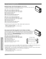


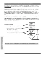


#4 top pin makes stack total 23.
#12 buildup pin makes stack
height 19 for control.
#2 master pin makes #7 cut
of change key work.
#5 bottom pin for #5 cut of TMK
change key cut is 7
Section 3 - 18
K
e
y
C
u
tt
in
g
&
P
in
n
in
g
4
12
2
5
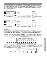
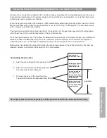
A small format interchangeable core pinning chart is an expanded
key bitting array (KBA) that speeds pinning. At the left is a key bit-
ting array. The control combination is a change key that is set aside.
SOP stands for Sequence of Progression.
7
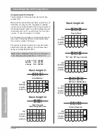
The inset at the left shows the pin stack for
the first change key possibility in the first
chamber.
The “7” from the KBA is in the large oval.
To the right of the oval are the pins needed
to make the #7 cut work with the #5 cut of
the top master key and the #9 cut of the
control key. Pin stacks are read from the
bottom up.
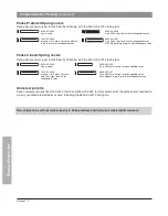
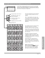
The complete pinning chart contains every
possible pin stack for every possible
change key and master key in the system.
To pin a core to a given key, find the bitting
of the key in each position in the large oval
and install the pins indicated in the squares
next to the oval.
The bottom row beneath the heading
“complete pin stacks for constants”, gives
complete pin stacks, including top pins, for
the rotating constant method, or for pinning
to master keys only.
Factory bitting lists come with pinning
charts. To make a pinning chart, fill in the
large ovals with the cuts in the key bitting
array, and do the pin stack calculations one
column at a time.
SKD’s and cross keying
SKD’s and cross keying cannot be pinned
from this chart. SKD’s are never master
keyed. Cross keying must be calculated
separately for each keying specification.
top
pins
complete pin stacks for constants
4
7
13
9
6
5
12
12
2
6
14
12
2
2
6
2
2
2
5
2
2
6
1
4
14
14
2
8
12
14
2
2
4
6
4
2
3
0
4
0
1
2
14
8
2
8
8
14
4
6
2
4
8
4
1
2
6
2
1
0
10
10
2
8
10
10
4
4
8
2
6
4
5
2
0
4
1
4
4
7
13
9
6
5
14
14
2
8
16
14
5
2
8
6
1
4
7
4
2
8
3
6
3
0
4
0
5
2
1
8
6
2
9
0
9
6
0
4
7
8
5
2
8
6
1
4
Control 9 6 0 4 7 8
TMK 5 2 8 6 1 4
7 4 2 8 3 6
3 0 4 0 5 2
1 8 6 2 9 0
9 6 0 4 7 8
SOP a b c d e f
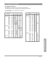
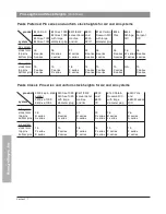
A2 System Small Format Interchangeable Core Pinning Charts
Содержание Peaks Preferred
Страница 1: ...Technical Manual Preferred Classic ...
Страница 3: ...Peaks Preferred Classic Notes ...
Страница 4: ...Technical Manual Section 1 Introduction Preferred Classic ...
Страница 12: ...Technical Manual Section 2 Product Information Preferred Classic ...
Страница 19: ...Section 2 7 Product Information Peaks Preferred Classic Notes ...
Страница 41: ...Section 2 30 Product Information Peaks Preferred Classic Notes ...
Страница 42: ...Section 2 31 Product Information Peaks Preferred Classic Notes ...
Страница 43: ...Section 2 32 Product Information Peaks Preferred Classic Notes ...
Страница 44: ...Technical Manual Section 3 Key Cutting and Pinning Preferred Classic ...
Страница 66: ...Section 3 22 Key Cutting Pinning Peaks Preferred Classic Notes ...
Страница 67: ...Section 3 23 Key Cutting Pinning Peaks Preferred Classic Notes ...
Страница 68: ...Preferred Classic Technical Manual Section 4 Key Control Record Keeping ...
Страница 79: ...Section 4 11 Key Control Record Keeping Peaks Preferred Classic Notes ...
Страница 80: ...Preferred Classic Technical Manual Section 5 Cylinder Installation Guide ...
Страница 91: ...Section 5 11 Cylinder Installation Guide Peaks Preferred Classic Notes ...


