


3
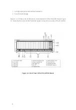
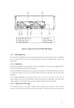
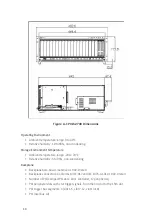
Figure 1-2 Rear View of the PXI-62700 chassis
1�3 OEM options
The standard PXI-62700 chassis includes backplanes and a power supply unit in addition
to the enclosure metal parts. The following sections depict the standard parts used in the
PXI-62700.
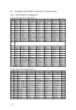
1�3�1 Backplane
PXI-62700 equipped with cBX-3018L, 18-slot PXI backplane. Please refer to Appendix B for
more technical information of the backplane.
Besides the standard backplanes, we provide more options for OEM customers, as long as
the request backplane is PXI or 3U CompactPCI form factor compliant with 21-slot width
limitation.
For example, application may require 32-bit only, rear I/O, or may need to use custom
power supply connector and additional custom features on the backplane. JYTEK provides
custom design and manufacturing services. Please contact us for more details.
1�3�2 Chassis Color and Logo
The standard color of PXI-62700 is beige. JYTEK provides custom chassis color or paint
specific logo for OEM, with minimum order requirement. Please contact us for more details.
Содержание PXI-62700
Страница 4: ...III Warranty Policy 26...
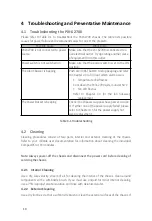
Страница 5: ...IV List of Tables Table 4 1 Troubleshooting 10...
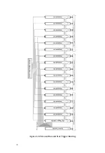
Страница 14: ...8 Figure 3 1 PXI Local Bus and Star Trigger Routing...


