


23
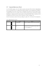
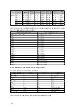
PCI VIO Selection Screw Terminals
Position
Signal Name
J1
+5V
J3
V(I/O)
J4
+3.3V
Note that the V(I/O) must be shorted to 3.3V or +5V. The default factory setting
is to short V(I/O) to +5V.
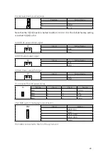
J6 INH#: DC power inhibit signal
J6
Pin #
Signal Name
1
INH#
2
GND
J8 RST#: System reset signal
J8
Pin #
Signal Name
1
RST#
2
GND
J9 FAL#: Power supply fail input
J9
Pin #
Signal Name
1
FAL#
2
GND
J5: Connector for LED power status
J5
Name
Pin #
Pin #
Name
GND
8
7
+3.3V
GND
6
5
+5V
GND
4
3
-12V
GND
2
1
+12V
CN2: SMB (system managing bus) connector
CN2
Pin #
Name
1
IPMB_CLK
2
GND
3
IPMB_DATA
4
IPMB_PWR
5
ALERT
The SMB is connected to the P2 of the system slot.
Содержание PXI-62700
Страница 4: ...III Warranty Policy 26...
Страница 5: ...IV List of Tables Table 4 1 Troubleshooting 10...
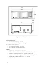
Страница 14: ...8 Figure 3 1 PXI Local Bus and Star Trigger Routing...