4-11
HOW TO USE THE BAR-CODE SCAN TOOL
Bar-Code Scan Tool inserts the Bar-code values (including Skew, Read power, HFM, LD power and so on) to
the Flash-ROM in the Loader Main Board. So, In case of changing the Traverse assembly or Loader main board,
It is required to pick-up Bar-code scan procedure.
1. BAR-CODE SCAN SYSTEM CONFIGURATION
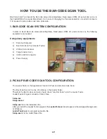
In order to insert Bar-code values (including Skew, Read power, HFM, LD power and so on), the following
equipments are needed.
Compulsory equipments
1) Personal
Computer
2) Bar-Code Scan Tool (Loader Tester)
3) 2D Bar-Code Scanner
4) Target Loader Ass’y
5) USB to SATA Connector
6) Power
Supply
2. PICK-UP BAR-CODE SCAN TOOL CONFIGURATION.
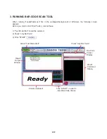
The Loader Tester is the Application Tool for FA Test and also Bar-Code Scan.
The Bar-Code Scan is the one of functions in the Loader Tester.
Therefore the Bar-Code scan Users should check “only Bar Code” up in the Loader Tester.
Loader Tester Program consists of total 2 files.
Setup.exe
Setup.exe.txt
Setup.exe
file is the installation file.
After you install the Loader Tester program, the
LoaderTest.exe
file will appear in the wallpaper(background)
of Windows.
LoaderTester.exe
is a program execution file.
Setup.exe
.txt is the install Report file.
Содержание XV-BP1B
Страница 13: ...2 6 MEMO ...
Страница 54: ...3 41 3 Video Part 1 100 Full Color bar 7 9 10 8 11 14 CVBS_I 7 Y 8 Pb 9 Pr 10 ...
Страница 55: ...3 42 4 Video Part 2 100 Full Color bar 9 8 11 14 13 12 CVBS 11 COMP_Y 12 COMP_Pb 13 COMP_Pr 14 ...
Страница 56: ...3 43 5 AUDIO PART S PDIF 15 17 16 18 19 21 ASPDIF 15 ...
Страница 57: ...3 44 6 HDMI PART 17 16 18 19 21 20 HDMI_SDA 16 HDMI_SCL 17 HDMI_CLK 18 HDMI_DATA 19 ...
Страница 58: ...3 45 7 FRONT I F PART 21 20 T_TX 20 R_RX 21 ...
Страница 59: ...3 46 BLOCK DIAGRAMS 1 OVERALL BLOCK DIAGRAM ...
Страница 60: ...3 47 2 SMPS BLOCK DIAGRAM ...
Страница 61: ...3 48 3 SYSTEM BLOCK DIAGRAM ...
Страница 62: ...3 49 4 MT8520 DDR2 SDRAM NAND FLASH EEPROM BLOCK DIAGRAM ...
Страница 63: ...3 50 5 MT8520 HDMI ETHERNET USB AV BLOCK DIAGRAM ...
Страница 65: ...3 52 7 SMPS POWER SIGNAL BLOCK DIAGRAM ...
Страница 66: ...3 53 8 MAIN BOARD POWER SIGNAL BLOCK DIAGRAM ...
Страница 68: ...3 55 10 LEVEL SHIFTER CEC EFUSE BLOCK DIAGRAM ...
Страница 69: ...3 56 MEMO ...
Страница 71: ...3 60 3 59 2 POWER TIMER USB CIRCUIT DIAGRAM ...
Страница 72: ...3 61 3 62 3 MT8520 1 CIRCUIT DIAGRAM ...
Страница 73: ...3 63 3 64 4 MT8520 2 CIRCUIT DIAGRAM ...
Страница 74: ...3 65 3 66 5 KEY CIRCUIT DIAGRAM ...
Страница 75: ...3 67 3 68 6 TIMER CIRCUIT DIAGRAM ...
Страница 76: ...3 69 3 70 7 DDR2 SDRAM CIRCUIT DIAGRAM ...
Страница 77: ...3 71 3 72 8 NAND FLASH ETHERNET CIRCUIT DIAGRAM ...
Страница 78: ...3 73 3 74 9 AV HDMI CIRCUIT DIAGRAM ...
Страница 79: ...3 75 3 76 PRINTED CIRCUIT BOARD DIAGRAMS 1 MAIN P C BOARD TOP VIEW BOTTOM VIEW ...
Страница 80: ...3 77 3 78 2 SMPS P C BOARD TOP VIEW BOTTOM VIEW ...
Страница 81: ...3 79 3 80 3 KEY P C BOARD TOP VIEW 4 TIMER P C BOARD TOP VIEW BOTTOM VIEW BOTTOM VIEW ...
Страница 105: ...4 24 MEMO ...
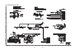
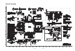
Страница 106: ...4 26 4 25 CIRCUIT DIAGRAM ...
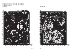
Страница 108: ...4 29 4 30 PRINTED CIRCUIT BOARD DIAGRAMS TOP VIEW ...
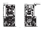
Страница 109: ...4 31 4 32 BOTTOM VIEW ...

