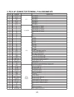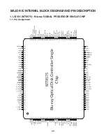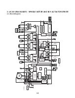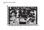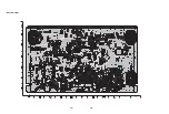
4-20
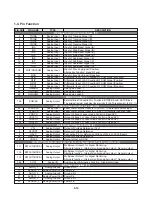
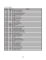
PIN NO
PIN NAME
TYPE
DESCRIPTION
31
AVDD12_3
Analog Power(1.2V) Power Pin
32
AVDD12_4
Analog Power(1.2V) Power Pin
43
AVDD33_4
Analog Power(3.3V) Power Pin
116
AVDD12_1
Analog Power(1.2V) Power Pin
127
AVDD33_1
Analog Power(3.3V) Power Pin
Low-Speed General Output (10)
33
LGO1P
Analog Output
Lowspeed General Output 1P
34
LGO1N
Analog Output
Lowspeed General Output 1N
35
LGO2P
Analog Output
Lowspeed General Output 2P
36
LGO2N
Analog Output
Lowspeed General Output 2N
37
LGO3P
Analog Output
Lowspeed General Output 3P
38
LGO3N
Analog Output
Lowspeed General Output 3N
39
LGO4P
Analog Output
Lowspeed General Output 4P
40
LGO4N
Analog Output
Lowspeed General Output 4N
41 LGO5P Analog
Output
Lowspeed General Output 5P
Alternative Function : Read gain switch 4
42 LGO5N Analog
Output
Lowspeed General Output 5N
Alternative Function : Read gain switch 5
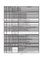
MOTOR (10)
50 FMO3 Analog
I/O
Feed motor 3 control. PWM output.
Alternative Function : Auxiliary servo input
51 FMO4 Analog
I/O
Feed motor 4 control. PWM output.
Alternative Function : Auxiliary servo input
52
TLO
Analog Output
Tilt servo output
53
TRO
Analog Output
Tracking servo output. PDM output of tracking servo compensator.
54
FOO
Analog Output
Focus servo output. PDM output of focus servo compensator.
55
TRAYPWM
Analog Output
Tray PWM control output. Controlled by
μ
P.
56
FMO
Analog Output
Feed motor control. PWM output.
57
FMO2
Analog Output
Feed motor 2 control. PWM output.
58
DMO
Analog Output
Disk motor control output. PWM output.
3.3V LVTTL I/O,
96 FG 5V-tolerance,1
Motor Hall sensor input. The pin is spike-free at power-on stage.
2mA
PDR,
75K
pull-up.
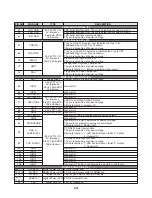
SATA Interface (10)
77
SVDD33
Analog Power(3.3V) Power supply for SATA 3.3V circuitry
78
SPLLVDD12 Analog Power(1.2V) Power supply for SATA circuitry
79
SAGND
Analog Ground
Ground Pin for SATA circuitry
80
STXVDD12
Analog Power(1.2V) Power supply for SATA transmit circuitry
81
STXP
Analog Output
Differential serial output transmit signal of SATA
82
STXN
Analog Output
Differential serial output transmit signal of SATA
83
SAGND
Analog Ground
Ground Pin for SATA circuitry
84
SRXN
Analog Input
Differential input receive signal of SATA
85
SRXP
Analog Input
Differential input receive signal of SATA
86
AVDD12_RX Analog Power(1.2V) Power supply for SATA circuitry
Crystal Interface (3)
74
XTAL25MI
Input
X`tal input. The working frequency is 25MHz.
75
XTAL25MO
Output
X`tal
output.
76
SXVDD33
Analog Power(3.3V) Power supply for X`ftal circuitry
Serial Flash (6)
97
SFHOLD#
Hold in normal serial flash mode but in quad I/O, as serial data input/data output
98
SFCLK
serial flashÅfs clock output
99
SFDO
serial data outputrial
100
SFCS#
chip select output
101
SFDI
serial data input
102 SFWP#
Write protection in normal serial flash mode but in quad I/O,
as serial data input/data output
3.3V LVTTL I/O,
5V-tolerance,
4,8,12,16mA PDR,
75K pull-up
Содержание XV-BP1B
Страница 13: ...2 6 MEMO ...
Страница 54: ...3 41 3 Video Part 1 100 Full Color bar 7 9 10 8 11 14 CVBS_I 7 Y 8 Pb 9 Pr 10 ...
Страница 55: ...3 42 4 Video Part 2 100 Full Color bar 9 8 11 14 13 12 CVBS 11 COMP_Y 12 COMP_Pb 13 COMP_Pr 14 ...
Страница 56: ...3 43 5 AUDIO PART S PDIF 15 17 16 18 19 21 ASPDIF 15 ...
Страница 57: ...3 44 6 HDMI PART 17 16 18 19 21 20 HDMI_SDA 16 HDMI_SCL 17 HDMI_CLK 18 HDMI_DATA 19 ...
Страница 58: ...3 45 7 FRONT I F PART 21 20 T_TX 20 R_RX 21 ...
Страница 59: ...3 46 BLOCK DIAGRAMS 1 OVERALL BLOCK DIAGRAM ...
Страница 60: ...3 47 2 SMPS BLOCK DIAGRAM ...
Страница 61: ...3 48 3 SYSTEM BLOCK DIAGRAM ...
Страница 62: ...3 49 4 MT8520 DDR2 SDRAM NAND FLASH EEPROM BLOCK DIAGRAM ...
Страница 63: ...3 50 5 MT8520 HDMI ETHERNET USB AV BLOCK DIAGRAM ...
Страница 65: ...3 52 7 SMPS POWER SIGNAL BLOCK DIAGRAM ...
Страница 66: ...3 53 8 MAIN BOARD POWER SIGNAL BLOCK DIAGRAM ...
Страница 68: ...3 55 10 LEVEL SHIFTER CEC EFUSE BLOCK DIAGRAM ...
Страница 69: ...3 56 MEMO ...
Страница 71: ...3 60 3 59 2 POWER TIMER USB CIRCUIT DIAGRAM ...
Страница 72: ...3 61 3 62 3 MT8520 1 CIRCUIT DIAGRAM ...
Страница 73: ...3 63 3 64 4 MT8520 2 CIRCUIT DIAGRAM ...
Страница 74: ...3 65 3 66 5 KEY CIRCUIT DIAGRAM ...
Страница 75: ...3 67 3 68 6 TIMER CIRCUIT DIAGRAM ...
Страница 76: ...3 69 3 70 7 DDR2 SDRAM CIRCUIT DIAGRAM ...
Страница 77: ...3 71 3 72 8 NAND FLASH ETHERNET CIRCUIT DIAGRAM ...
Страница 78: ...3 73 3 74 9 AV HDMI CIRCUIT DIAGRAM ...
Страница 79: ...3 75 3 76 PRINTED CIRCUIT BOARD DIAGRAMS 1 MAIN P C BOARD TOP VIEW BOTTOM VIEW ...
Страница 80: ...3 77 3 78 2 SMPS P C BOARD TOP VIEW BOTTOM VIEW ...
Страница 81: ...3 79 3 80 3 KEY P C BOARD TOP VIEW 4 TIMER P C BOARD TOP VIEW BOTTOM VIEW BOTTOM VIEW ...
Страница 105: ...4 24 MEMO ...
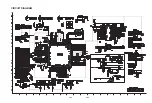
Страница 106: ...4 26 4 25 CIRCUIT DIAGRAM ...
Страница 108: ...4 29 4 30 PRINTED CIRCUIT BOARD DIAGRAMS TOP VIEW ...
Страница 109: ...4 31 4 32 BOTTOM VIEW ...

