3-5
3.3.5
Phase of control head (X value)
Note:
Remove the exterior parts attached to the UPPER CASE
ASSEMBLY so that the screws around the A/C HEAD
ASSEMBLY can be tighten or loosen.
(1) Connect the JIG CONNECTOR CABLE to CN25 on the
MAIN BOARD ASSEMBLY.
(2) Playback the SP stairstep signal of the alignment tape and
observe signal at V_TP_FM with external trigger from
V_FF on the JIG CONNECTOR CABLE.
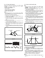
(3) Operate the tracking button in the center and manual
tracking mode by pressing the tracking (+) and (-) buttons
and confirm that the FM output level is maximum at
the center position as shown in Fig. 3-3-9.
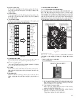
(4) If necessary, slightly loosen the setscrews D and E and
insert the Tweezers into the notch and guide hole to move
the A/C HEAD fully in the direction of the capstan to the
extent.
(5) Gradually move the A/C HEAD toward the drum to find the
position where the FM output level maximum for the first
time (a’ - b’ in Fig. 3-3-9).
(6) Fine adjust the phase of the A/C HEAD and tighten the
screws D and E at the point a.
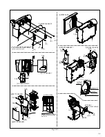
Fig.3-3-8
Fig.3-3-9
A/C HEAD
INSERT THE
TWEEZERS
SCREW E
SCREW D
A/C HEAD PHASE
DIRECTION OF DRUM
ZERO
DIRECTION OF CAPSTAN
FM OUTPUT
A
B
ADJUSTING
POINT
MAX
3.4 ELECTRICAL ADJUSTMENT
3.4.1
ELECTRICAL ADJUSTMENT WITH PERSONAL COM-
PUTER
• Electrical adjustment except for B/W VF ASSEMBLY is per-
formed by using PERSONAL COMPUTER. As for the cable
connection, see Fig. 3-1-1. Read README.TXT file to use the
software for SERVICE SUPPORT SYSTEM properly.
• Remove the COVER (JIG) to perform adjustment.
NOTE:
For the connection of the JIG CONNECTOR CABLE, refer to
Fig.3-1-1.
3.3.4
A/C head height & azimuth
Remove the exterior parts attached to the UPPER CASE
ASSEMBLY so that the screws around the A/C HEAD
ASSEMBLY can be tighten or loosen.
• LOWER CASE ASSEMBLY
• TOP OPE UNIT
• CASE COVER(S),(M) ASSEMBLY
• UPPER CASE (S),(M) ASSEMBLY
• FRONT FRAME ASSEMBLY
NOTE:
In performing adjustment, it is recommended that LOWER
CASE ASSEMBLY and TOP OPE UNIT are attached to the
main body for better operation and safety.
(1) Remove the Cover (JIG) shown on Fig.3-4-1.
(2) Connect the JIG CONNECTOR CABLE to CN25 on the
MAIN BOARD ASSEMBLY.
(3) Connect the channel-1 scope probe to the audio output
(AO_SIG_J) and connect the channel-2 scope probe to PB
CTL.
(4) Playback the alignment tape.
(5) Set the tracking to its center range by pressing the (+) and
(-) tracking controls simultaneously.
(6) Adjust screws A , B and C approximately 45 degrees in the
same direction to obtain maximum audio output and CTL
signal levels.
(7) As a final fine adjustment, adjust screw B for minimum sig-
nal level fluctuation and screw C for maximum output sig-
nal level
.
Fig.3-3-7
Fig.3-3-8
A/C HEAD
SCREW B
SCREW A
SCREW C
Audio
signal
Control
pulse
signal


