background image

1-2

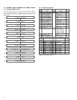
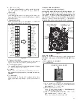
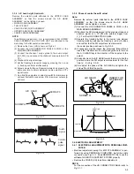
1.2 ASSEMBLY AND DISASSEMBLY OF CABINET PARTS

1.2.1

Disassembly flow chart

This flowchart indicates the disassembly step for the cabinet
parts and board assembly in order to gain access to item(s)
to be serviced. When reassembling, perform the step(s) in re-
verse order.

[1]

LOWER CASE ASSY

[2]

C. COVER ASSY

[3]

C. COVER INSIDE

[4]

BATT. COVER ASSY

[5]

BATT. CASE ASSY

[6]

UPPER CASE

[7]

FRONT COVER SA

[8]

FRONT FRAME ASSY

[9]

OP ASSY (inc. CCD BOARD ASSY)

[10]

MAIN BOARD ASSY

[11]

SHIELD PLATE

[12]

MECHANISM ASSY

1.2.2

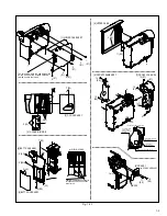
Disassembly method

[1]

LOWER CASE ASSEMBLY Fig.1-2-1 6(S1)

[2]

C.COVER ASSY

1(S2), 2(L2)

[3]

C.COVER INSIDE

4(L3)

[4]

BATT. COVER ASSY

2(L4)

[5]

BATT. CASE ASSY

4(S5), 2(L5)

[6]

UPPER CASE

1(S6), 2(L6)

[7]

FRONT COVER SA

2(S7), 2(L7), CN8

[8]

FRONT FRAME ASSY

2(S8)

[9]

OP ASSY

2(S9), CN22

[10]

MAIN BOARD ASSY Fig.1-2-2 2(S10), CN1(C3),

2(SD10), CN2(F3),

CN3(A2), CN4(D2),
CN5(E3), CN7(B2)

[11]

SHIELD PLATE

2(S11)

[12]

MECHANISM ASSY

3(S12), 2(L13)

STEP

No.

PART

NOTE

Fig.
No.

POINT

CONN.

No.

Pin No.

CONNECTOR

CN8

MAIN

CN8

MIC ASSY

2

CN22

MAIN

CN22

CCD

CN5301

16

CN1

MAIN

CN1

MECHANISM

10

CN2

MAIN

CN2

MECHANISM

14

CN3

MAIN

CN3

MECHANISM

18

CN4

MAIN

CN4

MECHANISM

2

CN5

MAIN

CN5

MECHANISM

11

CN7

MAIN

CN7

MECHANISM

11

Remove the parts marked in       .
Содержание VU-FC1KUS

Страница 1: ...atura de almacenamiento 20 C a 50 C Peso Aprox 590 g Algunos accesorios no se encuentran disponibles en ciertas áreas Por favor consulte a su agente más cercano de JVC antes de comprar los accesorios opcionales Los especifiaciones indicadas corresponden al modo SP a menos que se especifique lo contrario Diseño y especificaciones sujetos a cambio sin previo aviso Accesorios opcionales VHS Compacto ...

Страница 2: ...lue 3 5 3 4 ELECTRICAL ADJUSTMENT 3 6 3 4 1 ELECTRICAL ADJUSTMENT WITH PERSONAL COMPUTER 3 3 4 CHARTS AND DIAGRAMS 4 1 BOARD INTERCONNECTIONS 4 3 4 2 MAIN CPU SCHEMATIC DIAGRAM 4 5 4 3 MAIN M MDA SCHEMATIC DIAGRAM 4 7 4 4 MAIN DSP SCHEMATIC DIAGRAM 4 9 4 5 MAIN REG SCHEMATIC DIAGRAM 4 11 4 6 MAIN VTR ASP SCHEMATIC DIAGRAM 4 13 4 7 MAIN TG CDS SCHEMATIC DIAGRAM 4 15 4 8 CCD SCHEMATIC DIAGRAM 4 16 4...

Страница 3: ...e specified for compliance with recognized codes pertaining to X ray emission Consequently when servicing these products replace the cath ode ray tubes and other parts with only the specified parts Under no circumstances attempt to modify these circuits Unauthorized modification can increase the high voltage value and cause X ray emission from the cathode ray tube 12 Crimp type wire connector In s...

Страница 4: ...eter to measure across both terminals of load Z See figure 9 and following table 2 5 Grounding Class 1 model only Confirm specified or lower grounding impedance between earth pin in AC inlet and externally exposed accessible parts Video in Video out Audio in Audio out or Fixing screw etc Measuring Method Connect milli ohm meter between earth pin in AC inlet and exposed accessible parts See figure ...

Страница 5: ... unhooked unlocked released unplugged unclamped or unsoldered P Spring W Washer S Screw Unhook unlock release unplug or unsolder 2 S3 2 Screws S3 CN Connector 5 Adjustment information for installation 1 1 3 Destination of connectors Two kinds of double arrows in connection tables respec tively show kinds of connector wires Wire Flat wire FPC FFC Example Remove the parts marked in Fig 1 1 1 Connect...

Страница 6: ...Y 1 2 2 Disassembly method 1 LOWER CASE ASSEMBLY Fig 1 2 1 6 S1 2 C COVER ASSY 1 S2 2 L2 3 C COVER INSIDE 4 L3 4 BATT COVER ASSY 2 L4 5 BATT CASE ASSY 4 S5 2 L5 6 UPPER CASE 1 S6 2 L6 7 FRONT COVER SA 2 S7 2 L7 CN8 8 FRONT FRAME ASSY 2 S8 9 OP ASSY 2 S9 CN22 10 MAIN BOARD ASSY Fig 1 2 2 2 S10 CN1 C3 2 SD10 CN2 F3 CN3 A2 CN4 D2 CN5 E3 CN7 B2 11 SHIELD PLATE 2 S11 12 MECHANISM ASSY 3 S12 2 L13 STEP ...

Страница 7: ...STALLED i i 4 BATT COVER ASSY 5 BATT CASE ASSY 7 S5 8 S5 9 S5 10 S5 2 L4 L5 L5 e e 6 UPPER CASE 11 S6 L6 2 d A a d b c A b a c 12 S7 13 S7 7 FRONT COVER SA 8 FRONT FRAME ASSY 14 S8 15 S8 IC1601 THE SLACK OF WIRE IS PROCESSED IN THIS PART AS SHOWN IN FIGURE DRAWING FOR MIC WIRE ARRANGEMENT SO AS NOT TO PUT MIC WIRE ON IC601 FIGURE IS PROCESSED TO A ROLL DOWNWARD THE INDSIDE OF THIS BOSS IS PASS WIR...

Страница 8: ...AL POINT AT THE END IT HANGS IT TERMINALS ARE INSTALLED IN THE POSITION OF FIGURE A SIDE VIEW FRONT COVER SA a b c a c b PART A OF MIC CUSHION IS DRAWN OUT FROM THE HOLE DITCH PART B IS MADE TO ENTER AROUND ALL THESE PARTS MIC CUSHION INTERIOR OF MIC CUSHION AND MIC IS COVERED WITH MIC IS INSERTED IN THE AND PART c THE RIB OF MIC CAP IS PUT OUT FROM PART a PART b THE RABBER FRAME OF CUSHION MIC CA...

Страница 9: ...ded with a cassette tape and the cassette tape cannot be ejected with the EJECT button manually take it out of the set according to the following procedure NOTE If the mechanism comes into the unloading mode as the cas sette tape is not held by hand it results in tape damage 1 Disconnect the set from the power source 2 Remove the UPPER CASE refer to 1 2 ASSEMBLY AND DISASSEMBLY OF CABINET PARTS 3 ...

Страница 10: ...rew Reference drawing Screw tightening torque NOTE 1 Don t reuse the screw because screw lock bond was applied to them 2 Pay careful attention to tightening torque for each screw I 0 196N m 2 0kgf cm II 0 118N m 1 2kgf cm III 0 204N m 2 08kgf cm 1 2 11 12 10 5 9 6 7 8 I I I III I II Fig 1 3 1 Fig 1 3 2 1 3 DISASSEMBLY ASSEMBLY OF CABINET PARTS AND BOARD ASSEMBLY 1 2 3 4 5 6 7 8 9 10 11 12 13 14 15...

Страница 11: ...of wiring to chip test points for measurement use IC clips etc to avoid any stress b Since connectors are fragile carefully handle them in disconnecting and connecting c Short circuit between operation unit and DECK chas sis 2 Required test equipment a Color TV monitor b DC power supply c Oscilloscope dual trace type observable 100 MHz or higher frequency It is recommended to use one observable 30...

Страница 12: ...bar chart To be used for adjustment of the camera system For the us age of the INF adjustment lens refer to the Service Bulletin No YA SB 10035 9 INF lens holder To be used together with the Camera stand 11 for operating the Videocamera in the stripped down condition such as the status without the exterior parts or for using commodities that are not yet conformable to the interchangeable ring For ...

Страница 13: ...POLE POLE CASSETTE TORQUE METER 10 Light box assembly To be used for adjustment of the camera system For the us age of the Light box assembly refer to the Service Bulletin No YA SB 10035 11 Camera stand To be used together with the INF adjustment lens holder For the usage of the Camera stand refer to the Service Bulletin No YA SB 10035 12 Jig connector cable To be connected to the Jig connector ja...

Страница 14: ...lant of the A C HEAD to the tape So that the tape normally runs along the lower flange of the GUIDE POLE CH 2 CAUSER BY WRONG HEIGHT OF SUPPLY GUIDE ROLLER CAUSED BY WRONG HEIGHT OF TAKE UP GUIDE ROLLER FLATTEN WAVEFORM 1 field CORRECT VARIATION OF WAVEFORM BAD VARIATION OF WAVEFORM Fig 3 3 3 3 3 3 Tape pattern Remove the exterior parts attached to the UPPER CASE ASSEMBLY so that the guide roller ...

Страница 15: ...TER Electrical adjustment except for B W VF ASSEMBLY is per formed by using PERSONAL COMPUTER As for the cable connection see Fig 3 1 1 Read README TXT file to use the software for SERVICE SUPPORT SYSTEM properly Remove the COVER JIG to perform adjustment NOTE For the connection of the JIG CONNECTOR CABLE refer to Fig 3 1 1 3 3 4 A C head height azimuth Remove the exterior parts attached to the UP...

Страница 16: ...VICTOR COMPANY OF JAPAN LIMITED 12 3 chome Moriya cho Kanagawa ku Yokohama Kanagawa prefecture 221 8528 Japan AV MULTIMEDIA COMPANY Printed in Japan 0305 VP ...

Отзывы: