(No.MB127)1-9
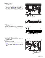
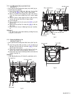
3.1.8 2.1.8 Removing the power transformer
(See Fig.11)
• Prior to perform the following procedures, remove the top cov-
er and front panel assembly.
(1) From the top side of main body, disconnect the wire from
the connector
CN202
on the AC power supply board.
(2) Remove the strain relief holding the power cord and re-
move the three screws
H
attaching the AC power supply
board.
(3) Lift the AC power supply board and remove the wire hold-
ers from the reverse side of the AC power board.
(4) Cut the tie band.
(5) Disconnect the wire from the connector
CN201
on the DC
power board.
(6) Disconnect the wire from the connector
CN702
on the rec-
tifier board.
(7) Remove the four screws
J
attaching the power transform-
er.
Reference:
• After attaching the front panel assembly, bundling the wires
using the new tie bands.
Fig.11
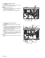
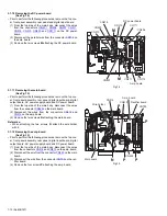
3.1.9 Removing the fan motor
(See Figs.12 and 13)
• Prior to perform the following procedures, remove the top cov-
er.
(1) From the top side of the main body, cut the tie bands and
disconnect the wire from the connector
CN207
on the DC
power board. (See Fig.12.)
(2) Remove the screw
K
and screw
K’
attaching the fan as-
sembly, then remove the fan assembly. (See Fig.12.)
(3) Remove the two screws
L
attaching the fan motor to the fan
bracket. (See Fig.13.)
Reference:
• After attaching the screw
K’
, attach the wire holder with it.
Fig.12
Fig.13
CN202
DC power board
Power cord
Wire holder
Rectifier board
AC Power supply board
Strain relief
CN201
CN702
Power transformer
Tie band
H
J
J
Fan assembly
DC power board
CN207
Tie bands
K
K'
Wire holder
L
Fan bracket
Fan moter

