


1-8 (No.MB127)
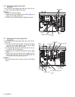
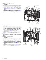
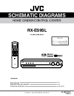
3.1.6
Removing the digital output board
(See Fig.9)
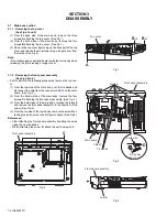
• Prior to perform the following procedures, remove the top cov-
er, tuner, rear panel and digital input board.
Reference:
• Remove the tuner as required.
(1) Disconnect the card wires from the connectors
CN513
and
CN514
on the digital output board.
(2) Remove the screw
G
attaching the digital output board.
Fig.9
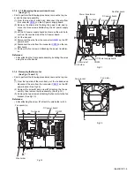
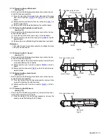
3.1.7
Removing the AC power supply board
(See Fig.10)
• Prior to perform the following procedures, remove the top cov-
er and tuner.
(1) From the top side of the main body, disconnect the power
cord from the connector
CN203
on the AC power supply
board and remove it from the rear panel.
(2) Cut the tie bands and disconnect the wire from the connec-
tor
CN218
on the DC power board.
(3) Remove the three screws
H
attaching the AC power supply
board.
(4) Disconnect the wire from the connector
CN202
on the AC
power supply board and remove the wire holders from the
reverse side of the AC power supply board.
Reference:
• When attaching the three screws
H
, attach the wire holder
with it.
Fig.10
Card wires
Digital output board
CN513
CN514
G
CN202
CN203
DC power board
Power cord
CN218
AC power supply board
Wire holder
Rear panel
Tie bands
H
H
Wire
holder
Wire
holder


