


(No.MB127)1-7
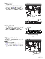
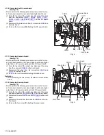
3.1.3 Removing the tuner
(See Figs.5 and 6.)
• Prior to perform the following procedures, remove the top cov-
er.
(1) From the top side of the main body, disconnect the card
wire from the connector
CN1
on the tuner. (See Fig.5.)
(2) From the back side of the main body, remove the two
screws
E
attaching the tuner to the rear panel. (See Fig.6.)
Fig.5
Fig.6
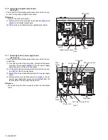
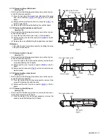
3.1.4 Removing the rear panel
(See Fig.7)
• Prior to perform the following procedures, remove the top cover.
(1) From the back side of the main body, remove strain relief
from the rear panel in the direction of the arrow.
(2) Remove the twenty screws
F
attaching the rear panel.
Fig.7
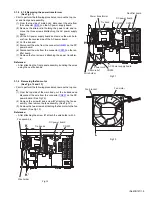
3.1.5 Removing the digital input board
(See Fig.8)
• Prior to perform the following procedures, remove the top cov-
er, tuner and rear panel.
Reference:
• Remove the tuner as required.
(1) From the top side of the main body, remove the connector
CN521
on the digital input board in an upward direction.
(2) From the reverse side of the digital input board, disconnect
the card wire from the connector
CN522
on the digital input
board.
Fig.8
Card wire
Tuner
CN1
E
Rear panel
F
F
Rear panel
Strain relief
Digital input board
CN522
CN521


