(No.MB127)1-11
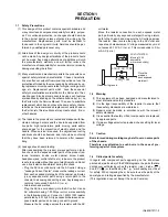
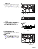
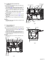
3.1.13 Removing the rectifier board
(See Fig.16)
• Prior to perform the following procedures, remove the top cov-
er and front panel assembly.
(1) From the top side of the main body, disconnect the wires
from the connectors
CN702
and
CN703
on the rectifier
board.
(2) Disconnect the parallel wire from the connector
CN711
on
the DC power board.
(3) Remove the two screws
Q
attaching the rectifier board.
3.1.14 Removing the headphone jack board
(See Fig.16)
• Prior to perform the following procedures, remove the top cov-
er and the front panel.
(1) From the top side of the main body, cut the tie bands.
(2) Disconnect the wire from the connector
CN206
on the DC
power board.
(3) Remove the screw
R
attaching the headphone jack board.
Reference:
• After attaching the front panel assembly, bundling the wires
using the new tie bands.
Fig.16
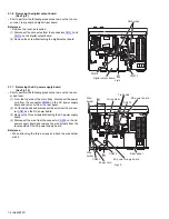
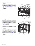
3.1.15 Removing the FL board
(See Fig.17)
• Prior to perform the following procedures, remove the top cov-
er and front panel assembly.
(1) From the inside of the front panel assembly, remove the six
screws
S
attaching the FL board.
(2) Disconnect the wire from the connector
CN403
on the FL
board.
(3) Disconnect the connector
CN401
on the FL board in an up-
ward direction.
3.1.16 Removing the volume board
(See Fig.17)
• Prior to perform the following procedures, remove the top cov-
er and front panel assembly.
(1) From the inside of the front panel assembly, remove three
screws
T
attaching the volume board.
(2) Disconnect the wire from the connector
CN403
on the FL
board.
Fig.17
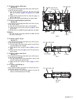
3.1.17 Removing the SW board
(See Fig.18)
• Prior to perform the following procedure, remove the top cover,
front panel assembly and FL board.
(1) From the inside of the front panel assembly, remove the
seven screws
U
attaching the SW board.
Fig.18
CN206
DC power board
Headphone jack board
Rectifier board
CN703
CN702
CN711
Tie band
R
Q
Q
T
S
Front panel assembly
FL board
Volume board
CN403
CN401
U
Front panel assembly
SW board

