RC-BM5
1-15
1
2
Fig.3
Fig.4
Cassette mechanism assembly
Flywheel assembly
Capstan motor
Capstan motor
belt
Fig.2
B
Capstan motor
Bracket
A
Fig.5
Cassette mechanism
assembly
Flywheel assembly
Shaft
Slit washer
Flywheel assembly
Main belt
Pinch roller
arm
assembly
REC/PB head
Erase head
Washer
Spring
Notch
b
C
F
E
D
Fig.1
Claw
a
Leaf switch
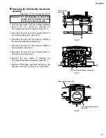
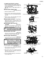
Removing the capstan motor
(See Figs.1 and 2.)
1.
2.
3.
Remove the capstan motor belt.
Remove the two screws
A
retaining the bracket of
the capstan motor from the cassette mechanism
assembly.
Remove the two screws
B
retaining the bracket
from the capstan motor. (See Fig.2.)
Prior to performing the following procedures,
remove the cassette mechanism assembly from
the rear cabinet assembly.
(See Fig.17 and 18 of "Rear cabinet section" on
page 1-10.)
[Note]
In the assembly, hang the notch b of the
pinch roller arm assembly to the spring.
1.
2.
3.
From the bottom side of the cassette mechanism
assembly, remove the main belt.
From the top side of the cassette mechanism
assembly, remove the slit washer retaining the
shaft of the flywheel assembly.
Pull out the flywheel assembly in the direction of
the arrow. (See Fig.5.)
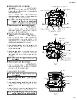
Removing the flywheel assembly
(See Figs. 4 and 5.)
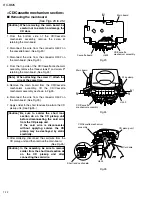
<Cassette mechanism section>
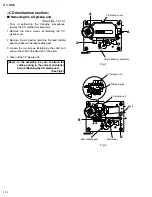
Removing the leaf switch
(See Fig.3.)
Pressing the claw
a
of the leaf switch in the
direction of the arrow
1
and take out the leaf switch
in the direction of the arrow
2
.
Removing the pinch roller arm
assembly
(See Fig.4.)
Remove the screw
C
retaining the pinch roller arm
assembly and remove the pinch roller arm
assembly in an upward direction.
Removing the erase head
(See Fig.4.)
Remove the screw
D
retaining the erase head and
remove the erase head in an upward direction.
Removing the REC/PB head
(See Fig.4.)
Remove the screw
E
, washer and screw
F
retaining
the REC/PB head and remove the REC/PB head.
[Notes] When removing or replacing the
REC/PB head, perform the REC/PB head
adjustment. (See "Adjustment method".)
After adjusting the REC/PB head, apply
a locking agent to the screws F.
Содержание RC-BM5
Страница 41: ...RC BM5 2 1 A B C D E F G 1 2 3 4 5 Block diagram ...
Страница 48: ...RC BM5 2 8 RC BM5 H A B C D E F G 1 2 3 4 5 Printed circuit boards Main board Reverse side ...
Страница 49: ...RC BM5 2 9 A B C 1 2 3 4 5 Tuner board Cassette board Reverse side Reverse side ...
Страница 50: ...RC BM5 2 10 A B C D 1 2 3 4 5 Display board Reverse side Power amplifier board Reverse side ...
Страница 51: ...RC BM5 2 11 A B C 1 2 3 4 5 Volume switch board Reverse side Phone jack board Reverse side ...

