3-1
SECTION 3
ADJUSTMENT
3.1.1 Precaution
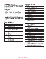
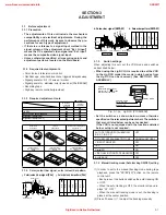
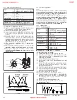
3.1.3 Required adjustment tools
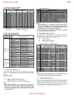
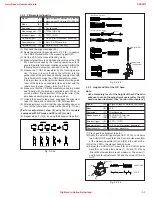
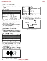
3.1.4 Color (colour) bar signal, color (colour) bar pattern
Fig. 3-1-4a Jig RCU [PTU94023B]
3.1.5
Switch settings
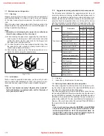
When adjusting this unit, set the VCR mode and switches
as described below.
• When using the Jig RCU, it is required to set the VCR
to the Jig RCU mode (the mode in which codes from
the Jig RCU can be received). (See SECTION 1 DIS-
ASSEMBLY.)
• Set the switches as shown below unless otherwise
specified on the relevant adjustment chart. The switches
that are not listed below can be set as desired.
If the VCR is not equipped with the functions detailed
below, setup is not required.
• The adjustments of this unit include the mechanism
compatibility and electrical adjustments. During the
performance of this work, be sure to observe the pre-
cautions for each type of adjustment.
• If there is a reference to a signal input method in the
signal column of the adjustment chart, “Ext. S-input”
means the Y/C separated video signal and “Ext. input”
means the composite video signal input.
• Unless otherwise specified, all measuring points and
adjustment parts are located on the Main board.
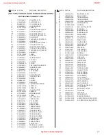
INITIAL MODE
DATA CODE
CUSTOM CODE
43: A
CODE
[Data transmitting method]
Depress the “ ” ( 3 ) button
after the data code is set.
Jig RCU
AUTO PICTURE/VIDEO CALIBRATION/
OFF
B.E.S.T./D.S.P.C.
PICTURE CONTROL/SMART PICTURE
NORMAL/NATURAL
VIDEO STABILIZER
OFF
TBC
ON
Digital 3R
ON
VIDEO NAVIGATION/TAPE MANAGER
OFF
BLUE BACK
OFF
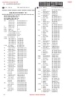
3.1.2 Required test equipments
• Color (colour) television or monitor
• Oscilloscope: wide-band, dual-trace, triggered delayed sweep
• Signal generator: RF / IF sweep / marker
• Signal generator: stairstep, color (colour) bar [PAL/SECAM]
• Recording tape
• Digit-key remote controller(provided)
(75%)
White(75%)
0.7 V
0.3 V
Horizontal sync
V
U
1V
White(100%)
Yellow
Cyan
Green
Magenta
Red
Blue
Burst
0.3 V
V(R-Y)
U(B-Y)
White
Yellow
Cyan
Green
Magenta
Red
Blue
U
Black
White
100%
V
•
Color(colour) bar signal [PAL]
•
Color(colour) bar pattern [PAL]
: Used : Not used
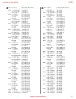
Machanism
compatibility
adjustment
Electrical
adjustment
Roller driver
Jig RCU
Back tension cassette gauge
Alignment tape(MHPE)
Alignment tape(MHPE-L)
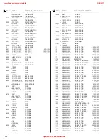
Roller driver
PTU94002
Back tension cassette gauge
PUJ48076-2
Jig RCU
PTU94023B
Alignment tape
(SP, stairstep, PAL)
MHPE
Alignment tape
(EP, stairstep, NTSC)
MHP-L
Alignment tape
(LP, stairstep, PAL)
MHPE-L
3.1
Before adjustment
3.1.6
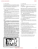
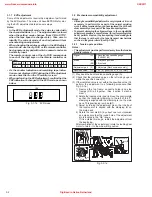
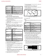
Manual tracking mode (Auto tracking ON/OFF) setting
(1) In order to set to the manual tracking mode during tape
playback, press the "SP/EP(LP)" button on the remote
control unit.
• Each press of the button switches the auto tracking ON
or OFF.
• When the auto tracking is OFF, the monitor screen dis-
plays “AT: OFF”.
• When the manual tracking mode is set, the tracking is
placed at the center position.
(2) Press "c/-" to adjust the tracking manually.
0.3 Vp-p
0.7 Vp-p
R-Y
B-Y
R-Y
B-Y
Cyan
Carrier(4.250 MHz)
Horizontal sync
Blue
Red
Magenta
Green
White (100%)
Yellow
White (100%)
Carrier(4.406 MHz)
B-Y colour BAR
R-Y colour BAR
White
Yellow
Cyan
Green
Magenta
Red
Blue
B–Y
Black
White
100%
R–Y
s
Colour bar signal [SECAM]
s
Colour bar pattern [SECAM]
www.freeservicemanuals.info
3/28/2017
Digitized in Heiloo Netherland

