(No.YA337)1-37
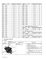
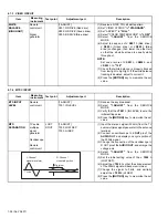
4.7.2 DRIVE CIRCUIT
Item
Measuring
instrument
Test point
Adjustment part
Description
DRIVE
CONVERGENCE
Remote
control unit
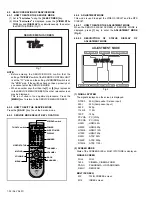
[9.RGB BOX PATTERN]
(1) Set to
"0 minutes"
using the
[SLEEP TIMER]
key.
(2) Press the
[VIDEO STATUS]
key and
[DISPLAY]
key simultaneously, to enter the
SERVICE MODE.
(3) Press the
[9]
key, to select "
RGB BOX
PATTERN MODE
" from the SERVICE MODE.
(4) Set the adjustment color mode to "
R
" to set the
red color adjustment mode.
(5) At Horizontal RGB box pattern, adjust the top
edge position as same or less than 0.5 pixel
hight as green.
(6) At Vertical RGB box pattern, adjust the right
edge position as same or less than 0.5 pixel
hight as green.
(7) Set the adjustment color mode to "
B
" to set the
blue color adjustment mode.
(8) At Horizontal RGB box pattern, adjust the top
edge position as same or less than 0.5 pixel
hight as green.
(9) At Vertical RGB box pattern, adjust the right
edge position as same or less than 0.5 pixel
hight as green.
(10) Check to see that the cross pattern is white. If
the cross pattern is not white, repeat the step
4. to 9. as abobe.
NOTE:
• Green is a fixed. (It can not be removed.)
• With this adjustment mode, the changed data is
written in the MEMORY instantly.
DRIVE CENTER
POSITION
Remote
control unit
Signal
generator
[9.RGB BOX PATTERN]
(1) Receive a center cross (or crosshatch) pattern.
(2) Set to
"0 minutes"
using the
[SLEEP TIMER]
key.
(3) Press the
[VIDEO STATUS]
key and
[DISPLAY]
key simultaneously, to enter the
SERVICE MODE.
(4) Press the
[9]
key, to select "
RGB BOX
PATTERN MODE
" from the SERVICE MODE.
(5) Set the adjustment color mode to "
R
G
B
" to set
the display position adjustment mode.
(6) Adjust the top and the bottom width to make
A
and
A"
even.
(7) Adjust the left and the right width to make
B
and
B"
even.
NOTE:
• With this adjustment mode, the changed data is
written in the MEMORY instantly.
R
Adjustment color
Horizontal RGB box pattern
Vertical RGB box pattern
Adjustment color
A
B
B"
A"
R
G
B
(B=B")
(A=A")


