(No.MB531)1-23
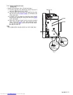
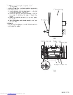
3.1.18 Removing the microphone amplifier board
(See Fig.25, 26)
• Remove the metal cover, front panel assembly and cassette B
mechanism assembly.
(1) From the front side of the front panel assembly, pull out the
microphone volume knob. (See Fig.25)
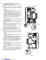
(2) From the inside of the front panel assembly, remove the
two screws
X
and remove the support 1 board. (See
Fig.26)
(3) Remove the screw
Y
and remove the support 2 board.
(See Fig.26)
(4) Take out the microphone amplifier board from the front
panel assembly.
References:
After attaching the microphone amplifier board, fix the card
wire the spacer as before.
Fig.25
Fig.26
Front panel assembly
Microphone
volume knob
Support 2 board
Spacer
Front panel assembly
Support 1 board
Microphone amplifier board
Y
X
Содержание DX-T66EE
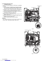
Страница 25: ... No MB531 1 25 Fig 3 Fig 4 Fig 5 Open det lever b Tray assemblies Side R assembly c Tray assembly ...
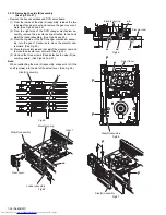
Страница 38: ...1 38 No MB531 Fig 36 Fig 37 Main tray Sub tray Tray stopper Tray stopper ...
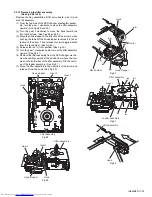
Страница 40: ...1 40 No MB531 Fig 3 Fig 4 Fig 5 Open det lever b Tray assemblies Side R assembly c Tray assembly ...
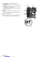
Страница 53: ... No MB531 1 53 Fig 36 Fig 37 Main tray Sub tray Tray stopper Tray stopper ...
Страница 65: ... No MB531 1 65 SECTION 5 TROUBLESHOOTING This service manual does not describe TROUBLESHOOTING ...
Страница 149: ...3 51 MEMO ...


