(No.MB531)1-55
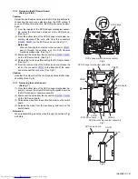
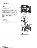
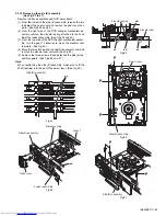
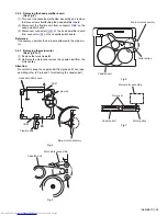
3.4.2 Removing the head amplifier board
(See Fig.4)
(1) Turn over the cassette mechanism assembly and remove
the three screws
A
attaching the head amplifier board.
(2) Disconnect the flexible wire from connector
CN8
on the
head amplifier board.
(3) Disconnect connector
CN41
of the head amplifier board
from connector
CN1
on the cassette switch board.
Reference:
If necessary, unsolder the 4-pin wire soldered to the main mo-
tor.
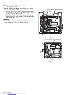
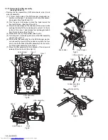
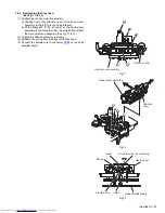
3.4.3 Removing the main motor
(See Fig.4 to 7)
(1) Remove the two screws
B
.
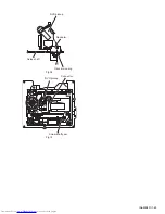
(2) Half raise the motor and remove the capstan belt from the
motor pulley.
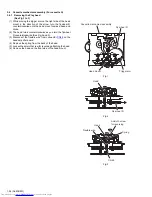
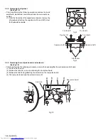
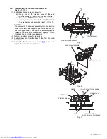
Attention:
Be careful to keep the capstan belt from grease. When reas-
sembling, refer to Fig.6 and 7 for attaching the capstan belt.
Fig.4
Fig.5
Fig.6
Fig.7
Head amplifier board
A
A
CN48
CN41
4pin wire
Flexible wire
Main motor assembly
A
B
Main motor assembly
Capstan belt
Main motor assembly
Capstan belt
Motor pulley
Main motor assembly
Capstan belt
Fly wheel
Motor pulley
Содержание DX-T66EE
Страница 25: ... No MB531 1 25 Fig 3 Fig 4 Fig 5 Open det lever b Tray assemblies Side R assembly c Tray assembly ...
Страница 38: ...1 38 No MB531 Fig 36 Fig 37 Main tray Sub tray Tray stopper Tray stopper ...
Страница 40: ...1 40 No MB531 Fig 3 Fig 4 Fig 5 Open det lever b Tray assemblies Side R assembly c Tray assembly ...
Страница 53: ... No MB531 1 53 Fig 36 Fig 37 Main tray Sub tray Tray stopper Tray stopper ...
Страница 65: ... No MB531 1 65 SECTION 5 TROUBLESHOOTING This service manual does not describe TROUBLESHOOTING ...
Страница 149: ...3 51 MEMO ...

