1-22 (No.MB531)
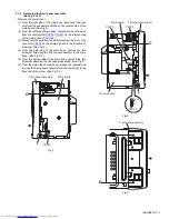
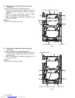
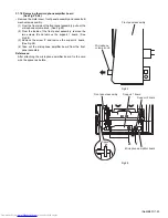
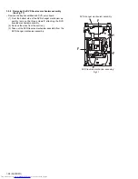
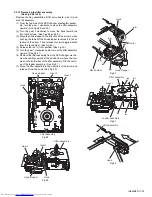
3.1.16 Removing the cassette A mechanism assembly
(See Fig.23)
• Remove the metal cover and front panel assembly.
(1) From the inside of the front panel assembly, remove the
four screws
V
and
W
attaching the cassette A mechanism
assembly.
(2) Disconnect the card wires from the connectors (
CN46
,
CN47
) on the cassette A mechanism assembly.
(3) Take out the cassette A mechanism assembly from the
front panel assembly.
Reference:
Remove the trans shield as required.
Fig.23
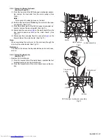
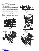
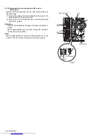
3.1.17 Removing the cassette B mechanism assembly
(See Fig.24)
• Remove the metal cover and front panel assembly.
(1) From the inside of the front panel assembly, remove the
four screws
V
and screw
W
attaching the cassette B mech-
anism assembly.
(2) Take out the cassette B mechanism assembly from the
front panel assembly.
Reference:
Remove the trans shield as required.
Fig.24
Cassette A mechanism assembly
Front panel assembly
Trans shield
V
CN47
CN46
V
V
V
W
Cassette B mechanism assembly
Front panel assembly
Trans shield
W
V
V
V
V
Содержание DX-T66EE
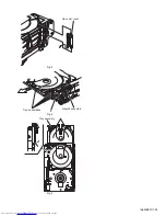
Страница 25: ... No MB531 1 25 Fig 3 Fig 4 Fig 5 Open det lever b Tray assemblies Side R assembly c Tray assembly ...
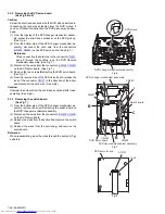
Страница 38: ...1 38 No MB531 Fig 36 Fig 37 Main tray Sub tray Tray stopper Tray stopper ...
Страница 40: ...1 40 No MB531 Fig 3 Fig 4 Fig 5 Open det lever b Tray assemblies Side R assembly c Tray assembly ...
Страница 53: ... No MB531 1 53 Fig 36 Fig 37 Main tray Sub tray Tray stopper Tray stopper ...
Страница 65: ... No MB531 1 65 SECTION 5 TROUBLESHOOTING This service manual does not describe TROUBLESHOOTING ...
Страница 149: ...3 51 MEMO ...

