background image

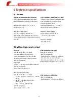
5.3 Video signalling

LEDs are present near the video connectors.

- Green means valid video signal presence and locked

- Off means no or invalid signal

5.4 Audio/Remote

Head Unit Audio - Headset

Use dynamic microphone

Max input level: -30dBu (25 mV rms) 

All headset impedance are allowed.

Audio - Intercom

4 wires - Line level (+22dBm) - 2 wires not 

supported

- Audio Level: +24dB maximum (+24dBu = 0dBfs)

- Bandwidth: 20Hz - 20kHz ± 0,1 dB

- Input: 10kΩ, couplage AC

- Output: 50Ω

Remote 1

Signals RS-232/RS422 are compliant with 

standard

Warning: on Base Unit, the SubD9 connector 

p12V DC to power the remote, so direct 

connection to a computer is not possible.

Remote 2

Compliant with USB2 standard

Remote 3

RS-232 with TTL level (+5V)

Warning: on Base Unit, the MiniDIN connector 

p12V DC to power the remote.

Remote LANC

LANC with TTL level (+5V)

Warning: on Base Unit, the MiniJack connector 

p6V DC to power the remote.

Power Remote on Base Unit

Total current for all remotes power must not 

exceed 0.7A

-24-

CamiFlex Base Unit – Head Unit

Содержание CamiFlex FG-CAM-F4/U

Страница 1: ......

Страница 2: ...T OVERVIEW 8 2 3 BASE UNIT OVERVIEW 9 2 4 HEAD UNIT SHOOTING POSITION 10 2 4 1 FIBRE ROCKING SYSTEM 10 2 4 2 TALLY 10 2 5 CAMI VL MOUNTING 11 3 OPERATION 12 3 1 POWER UP 12 3 2 DC IN 12 3 3 DC OUT 12 3 4 HEADSET AUDIO SETTINGS HEAD UNIT 13 3 5 HEADSET LIST 13 3 6 AUDIO HEADSET 14 3 7 INTERCOM 14 3 8 GENLOCK 15 3 9 SDI 15 3 10 REMOTE RS232 RS422 REMOTE 1 15 3 11 REMOTE ETHERNET USB REMOTE 2 15 3 12...

Страница 3: ...EADSET IN OUT CONNECTION 19 4 2 HEAD UNIT PINOUT CONNECTORS 20 4 2 1 HEAD UNIT REMOTE USB LANC CONNECTIONS 20 4 2 2 HEAD UNIT INTERCOM IN OUT CONNECTION 21 4 2 3 HEAD UNIT HEADSET IN OUT CONNECTION 21 4 2 4 HEAD UNIT DC IN CONNECTION 22 4 2 5 HEAD UNIT DC OUT FOR CAMERA CONNECTION 22 4 2 6 HEAD UNIT EXTERNAL TALLY CONNECTION IN FRONT OF HEAD UNIT 22 5 TECHNICAL SPECIFICATIONS 23 5 1 POWER 23 5 2 V...

Страница 4: ...ible Both Base Unit and Head Unit must be connected together thanks to hybrid fiber Connection Base Unit or Head Unit to another equipment can cause failure and such use may cancel the guarantee The mechanical ground of the equipment must be grounded It is necessary to use an AC cord with Earth as the one supplied If you choose to use another power cord make sure it is appropriate 100 240V 50 60Hz...

Страница 5: ...t will increase the efficient use of natural resources For further information about recycling this product please contact your local services your ECO organization or the local authorities 1 4 Restriction of Hazardous Substances RoHS This product is compliant with directive 2012 19 UE restricts the use of the following six substances Lead Pb Mercury Hg Cadmium Cd Hexavalent chromium Cr6 Polybromi...

Страница 6: ...Head unit 1 x Genlock from Base to Head unit 2 x Tally Preview On Air integrated on the front of the Head Unit plus external Tally output via a jack connector 1 x RS 232 RS 422 configurable Remote Power remote 1 1 x USB Ethernet remote 2 U option 1 x RS 232 TTL remote 3 Remote Power 1 x LANC remote 4 Remote Power 1 x DC OUT 13 2V to power the camera up to 40 watts 200 meters contact us if more out...

Страница 7: ...amera by using the Cami VL adapter see picture below In this case the Head Unit can be powered through an external cable that connects the Head Unit DC IN to the DTAP DC output on the Cami_VL If you have an hybrid fiber power supply is available on the Head Unit DC OUT In this case the battery is not required and the Head Unit can power the camera by using an external cable connected between the H...

Страница 8: ... of the equipment to the power supply and the effect of possible overload protection against overcurrent and power cables A study of the characteristics of the equipment must be made It is necessary to check the reliability of the grounding of the equipment especially for shunt connection Special extended temperature range products can be produced on customer request All equipment connections are ...

Страница 9: ...t AC power input Optical Hybrid connection GENLOCK from Global Generator SDI OUT to Switcher SDI IN SDI IN from Switcher SDI OUT LANC MiniJack 2 5mm 3p Intercom IN XLR3p F Headset XLR 5p Intercom OUT XLR3p M Remotes 1 2 SubD9 F Remotes 3 MiniDIN 6p F RJ45 Ethernet With Loop LED green signal present FG CAM F4 Fischer FG CAM N4 Neutrik FG CAM L4 Lemo Optical option Tally A B SubD9 M ...

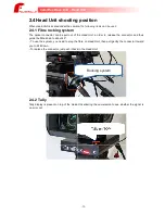
Страница 10: ...se the connector and thus guide the fibre down to about 45 To use the system you need to plug the fibre on Head Unit then pull gently the connector toward you to tilt it down To replace the connector just push it back in the Head Unit Rocking system 2 4 2 Tally Tally display is present on top of the Head Unit allowing the cameraman to see whether the signal is on air or not 10 CamiFlex Base Unit H...

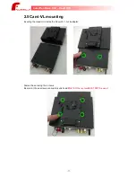
Страница 11: ... mounting Inserting the Head Unit inside the Cami VL V Lock adapter Fasten the set using the 4 crews Be careful those screws are countersunk head M3x10 Other screw MUST NOT be used 11 CamiFlex Base Unit Head Unit ...

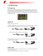
Страница 12: ...e power supply conveyed on the Hybrid Fibre 48V is internally converted by Head Unit for internal and external need 13 2V DC OUT see next section Hybrid Fiber 100 240V DC OUT 13 2V 40W Base Unit Head Unit Head unit can also be powered locally to give power redundancy Hybrid Fiber 100 240V DC IN 12V Base Unit Head Unit b Through local power supply Head Unit is powered by DC IN connector From 8V to ...

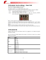
Страница 13: ...taneously Talk and buttons during 5 seconds LED flashing LED will then remain still to indicate that factory settings has been applied By default the factory settings are Mode1 PushToTalk with medium audio level Settings are saved automatically 10 seconds after each change and are recalled after each new boot 3 5 Headset list Headsets needs XLR 5 points and Female connector to be plugged on to the...

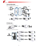
Страница 14: ...ND MIC GND L R Headset XLR5 XLR5 3 7 Intercom 4 wires intercom connection 4 wires intercom connection with 3 Head units Hybrid Fiber Base Unit Head Unit GND OUT OUT IN IN Headset GND MIC GND L R Headset XLR5 XLR5 Hybrid Fiber Head Unit GND MIC GND L R Headset XLR5 Hybrid Fiber Head Unit GND MIC GND L R Headset XLR5 300R 300R 300R 300R 300R 300R Base Unit XLR5 Base Unit XLR5 GND OUT OUT IN IN Heads...

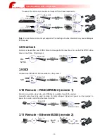
Страница 15: ...the insertion of an extra PAL NTSC video stream view finder Teleprompter Hybrid Fiber PAL NTSC Base Unit Head Unit BNC Genlock BNC Genlock 3 9 SDI A bidirectional SD HD 3G SDI is available on the product Hybrid Fiber SDI Base Unit Head Unit BNC SDI In BNC SDI Out BNC SDI Out BNC SDI In 3 10 Remote RS232 RS422 remote 1 Serial communication any rate up to 900Kbps is available thought the system A sp...

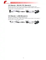
Страница 16: ...rom the Base Unit side Hybrid Fiber Base Unit Head Unit MiniDIN6 HRS20 With special cable MiniDIN6 MiniDIN6 3 13 Remote LANC Remote 4 LANC remote communication is available thought the system A specific cable has to be used on Head Unit side Hirose 20 type and power can be injected to power the remote control from the Base Unit side Hybrid Fiber Base Unit Head Unit Jack HRS20 With special cable Ja...

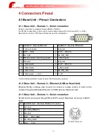
Страница 17: ...d 5 Ground 5 Ground 6 Not used 6 OUT RS_TX 7 Not used 7 Not used 8 Not used 8 IN RS_RX 9 Not used 12V 9 12V Note Differential RS 422 inputs includes 120R termination resistors 4 1 2 Base Unit Remote 2 Ethernet USB on Head Unit Ethernet RJ45 on Base side is used to connect a remote control or other to the camera through a dedicated Ethernet or USB cable on Head unit side 4 1 3 Base Unit Remote 3 Se...

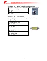
Страница 18: ... LANC 2 6V 3 GND 4 1 5 Base Unit Tally connection Tally input pins need to be in short circuit with ground to turn ON the Tally LED Tally A Red light Tally B Yellow light Both A B Tally Red light Pin SubD9 M Tally A B 1 Not used 2 Not used 3 Not used 4 Not usedn 5 Not used 6 Tally A Red 7 Ground 8 Tally B Yellow 9 Not used 18 CamiFlex Base Unit Head Unit ...

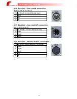
Страница 19: ...N Line level 1 GND 2 IN 3 IN 4 1 7 Base Unit Intercom OUT connection Standard XLR 3p connection Pin XLR 3p M Intercom OUT Line level 1 GND 2 OUT 3 OUT 4 1 8 Base Unit Headset IN OUT connection Pin XLR 5p F Headset IN OUT Line level 1 GND 2 OUT 3 OUT 4 IN 5 IN 19 CamiFlex Base Unit Head Unit ...

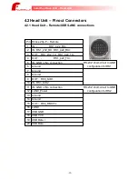
Страница 20: ..._TX 4 OUT RS1_422_TX 5 IN GND or No connection RS 232 short circuit to GND 6 Ground configuration for RS1 7 Ground 8 Ground 9 OUT RS3_SID1 10 IN RS3_SID2 11 IN GND or No connection RS 232 short circuit to GND 12 LANC_Power configuration for RS2 13 Ground 14 Ground 15 OUT RS3_RM CTL 16 LANC 17 USB GND 18 USB VCC 19 USB Data 20 USB Data 20 CamiFlex Base Unit Head Unit ...

Страница 21: ... IN OUT connection Pin Hirose 6p F Intercom IN OUT Line level 1 GND 2 IN 3 IN 4 GND 5 OUT 6 OUT 4 2 3 Head Unit Headset IN OUT connection Pin XLR 5p F Headset IN OUT 1 GND 2 Micro 3 GND 4 L 5 R 21 CamiFlex Base Unit Head Unit ...

Страница 22: ...GND 2 GND 3 12V or 13 2V 4 12V or 13 2V 5 Pin5 Pin5 not connected Vout 12V Pin5 connected to GND Vout 13 2V 4 2 6 Head Unit external Tally connection in front of Head Unit Pin Jack 3 5mm external Tally 1 GND not used 2 GPO grounded when turn ON LED 3 5V out protected with Fuse Recommended schematics Max current 100mA R depend on LED specification 22 CamiFlex Base Unit Head Unit R 5V out GPO 1 2 3 ...

Страница 23: ...Unit DC Out Max 40W 13 2V 5 2 Video input and output SDI Input SD HD and 3G SDI up to 3 Gbit s Automatic detection of video format Cable Equalization up to 100m in 3G SDI 800mVcc nominal level 500mVcc minimal BNC 75Ω impedance Loop output Copy of the input signal with cable equalization BNC 75Ω impedance Nominal Level 800mV 10 SDI output SD HD and 3G SD HD and 3G SDI up to 3 Gbit s 3G SDI 2 970Gbi...

Страница 24: ... dB Input 10kΩ couplage AC Output 50Ω Remote 1 Signals RS 232 RS422 are compliant with standard Warning on Base Unit the SubD9 connector provide 12V DC to power the remote so direct connection to a computer is not possible Remote 2 Compliant with USB2 standard Remote 3 RS 232 with TTL level 5V Warning on Base Unit the MiniDIN connector provide 12V DC to power the remote Remote LANC LANC with TTL l...

Страница 25: ...ce Braket support 3 8 CAMI CART1 CAMI CART CamiFlex 12V Jack5 5 FGJ6P CAMI_JVC H5J5 5 21cm CamiFlex 12V Jack5 5 XLR4F FGJ6P1 CAMI_JVC H5J5 5X4 21cm60cm CamiFlex LANC RA USB FGJ6R1 CAMI_JVC H20J2 5cU2 19cm21cm BNC BNC 40cm FGJ6B CAMI_BB 40cm FGJ8 Accessories set for JVC HM850 890 camcoders Designation Reference U adaptor V_Lock to CamiFlex CAMI VL see section 2 4 CamiFlex 13 2V XLR4F FGJ8P CAMI_JVC...

Отзывы: