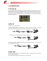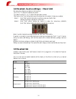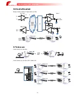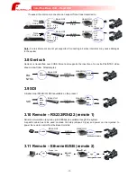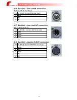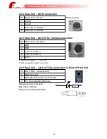
4.2.4 Head Unit – DC IN connection
Pin Hirose 4p-F – DC IN
External power
1
Ground
2
Ground
3
From +8V to +24V IN
4
From +8V to +24V IN
4.2.5 Head Unit – DC OUT for Camera connection
Pin Hirose 5p-F – DC OUT
1
GND
2
GND
3
+12V or +13.2V
(*)
4
+12V or +13.2V
(*)
5
Pin5 (*)
(*) Pin5 not connected:
Vout=+12V
(*) Pin5 connected to GND: Vout=+13.2V
4.2.6 Head Unit – external Tally connection in front of Head Unit
Pin Jack 3.5mm – external Tally
1
GND (not used)
2
GPO (grounded when turn ON LED)
3
+5V out (protected with Fuse)
Recommended schematics:
Max current: 100mA
R depend on LED specification
-22-
CamiFlex Base Unit – Head Unit
R
+5V out
GPO
1 2 3
Содержание CamiFlex FG-CAM-F4/U
Страница 1: ......

