

4 Connectors Pinout
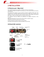
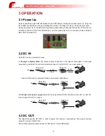
4.1 Base Unit – Pinout Connectors
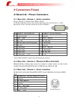
4.1.1 Base Unit – Remote 1 – Serial connection
Remote connection is managed through RS232 or RS-422.
For RS-232 configuration, a short-circuit must be done between Pin 4 & Ground (Pin 1 or Pin5).
Baud rate can be up to 700K baud without any specific configuration.
Pin SubD9-F - Remote RS-232
SubD9-F - Remote RS-422(*)
1
- (Do not used)
1
Ground
2
OUT : TxD
2
OUT : RS_TX-
3
IN : TxD
3
IN : RS_RX+
4
RS-4xx (short-circuit to ground)
4
- (Not used)
5
Ground
5
Ground
6
- (Not used)
6
OUT : RS_TX+
7
- (Not used)
7
- (Not used)
8
- (Not used)
8
IN : RS_RX-
9
- (Not used) → +12V
9
+12V
* Note: Differential RS-422 inputs includes 120R termination resistors
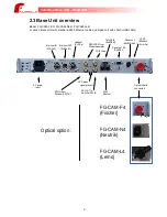
4.1.2 Base Unit – Remote 2 – Ethernet (USB on Head Unit)
Ethernet (RJ45) on Base side is used to connect a remote control or other to the
camera through a dedicated Ethernet or USB cable on Head unit side.
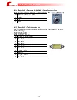
4.1.3 Base Unit – Remote 3 – Serial connection
Serial control can be sent through RS-232(TTL level). Baud rate can be up to 9600
baud.
Pin MiniDIN 6p-F - Remote RS232 (TTL level)
1
Ground
2
IN : RS3_RM/CTL
3
Ground
4
OUT : RS3_SID2
5
IN : RS3_SID1
6
OUT : +12V
-17-
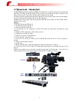
CamiFlex Base Unit – Head Unit
Female connector
Содержание CamiFlex FG-CAM-F4/U
Страница 1: ......