No. 51955
AV42PD20ES
28
ADJUSTMENT
■
MONITOR
Item
Measuring
instrument
Test point
Ad justment part
Description
Ad justment
of POWER
VOLTAGE
DC
voltmeter
Signal
generator
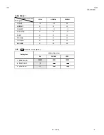
TP-1 (+5V)
TP-2 (
#
#
#
#
)
TP-3 (+170V)
TP-4 (+60V)
VR1 (+5)
VR3 (+170V)
VR4 (+60V)
*
*
*
*
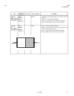
Ad justment of Vs(+170V) voltage.
1. Input the colour bar signal to RGB input terminal.
2. Connect the digital voltmeter across TP3 and TP2 (
#
).
3. Adjust the VR3 to s et the voltage within ±1V of the voltage (Vs
as s hown on the SERIAL LABEL) designed for the PDP module.
*
*
*
*
Ad justment of Vd(+60V) voltage.
1. Input the colour bar signal to RGB input terminal.
2. Connect the digital voltmeter across TP4 and TP2 (
#
).
3. Adjust the VR4 to s et the voltage within ±1V of the voltage (Vs
as s hown on the SERIAL LABEL) designed for the PDP module.
*
*
*
*
Ad justment of +5V voltage.
1. Input the colour bar signal to RGB input terminal.
2. Connect the digital voltmeter across TP1 and TP2 (
#
).
3. Confirm that the voltage of the TP1 and TP2 (
#
) have bec ome
5.1V±0.1V. If not, adjust the VR1 at the +5V ADJ of the POWER
PWB so that the voltage become 5.1V±0.1V.
■
RECEIVER
"
Under normal c onditions, no adjustment is required
confirmation adjustment.
Checking of
AFT CW VCO
Remote
control unit
1.VCO
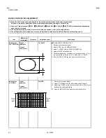
1. Select 1.IF from the SERVICE MENU.
2. Then select 1.VCO from the 1.IF SERVICE MENU (Fig.1).
3. Receive any broadc ast (55.75MHz or 216.00MHz is best).
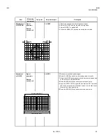
4. In the VCO adjustment screen, the yellow allows point (Fig.2) to
the characters. Chec k the yellow allow position where pointed to
the character from “ABOVE REF” to “BELLOW REF” (Fig.2 &
Fig.3).
*
The arrow position menu AFC voltage level.
TOO HIGH
ABOVE REF
JUST REF
BELOW REF
TOO LOW
i : EXIT
VCO(CW)
****
MHz
VC O M ENU
Fig.2
1. VCO
2. ATT ON/OFF
i : EXIT
IF SERVICE MENU
1-2 : SELECT
1. IF
Fig.1
TOO HIGH
ABOVE REF.
JUST REF.
BELOW REF.
t
V
(AFC)
TOO LOW.
Fig.3
Do no t select
this item
YELLOW
arrow

