background image

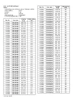
1-50 (No.YA097)

RHD107

(Not display) (Not display)

000

RHD108

(Not display) (Not display)

000

RHD109

(Not display) (Not display)

000

RHD110

(Not display) (Not display)

000

RHD111

(Not display) (Not display)

000

RHD112

(Not display) (Not display)

000

RHD113

(Not display) (Not display)

000

RHD114

(Not display) (Not display)

000

RHD115

(Not display) (Not display)

000

RHD116

(Not display) (Not display)

000

RHD117

(Not display) (Not display)

000

RHD118

(Not display) (Not display)

000

RHD119

(Not display) (Not display)

000

RHD120

(Not display) (Not display)

000

RHD121

(Not display) (Not display)

000

RHD122

(Not display) (Not display)

000

RHD123

(Not display) (Not display)

000

RHD124

(Not display) (Not display)

000

RHD125

(Not display) (Not display)

000

RHD126

(Not display) (Not display)

000

RHD127

(Not display) (Not display)

000

RHD128

(Not display) (Not display)

000

RHD129

(Not display) (Not display)

000

RHD130

(Not display) (Not display)

000

RHD131

(Not display) (Not display)

000

RHD132

(Not display) (Not display)

000

RHD133

(Not display) (Not display)

000

RHD134

(Not display) (Not display)

000

RHD135

(Not display) (Not display)

000

RHD136

(Not display) (Not display)

000

RHD137

(Not display) (Not display)

000

RHD138

(Not display) (Not display)

000

RHD139

(Not display) (Not display)

000

RHD140

(Not display) (Not display)

000

RHD141

(Not display) (Not display)

000

RHD142

(Not display) (Not display)

000

RHD143

(Not display) (Not display)

000

RHD144

(Not display) (Not display)

000

RHD145

(Not display) (Not display)

000

RHD146

(Not display) (Not display)

000

RHD147

(Not display) (Not display)

000

RHD148

(Not display) (Not display)

000

RHD149

(Not display) (Not display)

000

RHD150

(Not display) (Not display)

000

RHD151

(Not display) (Not display)

000

Item No.

Item name

Variable 

range

Initial setting 

value

RHD152

(Not display) (Not display)

000

RHD153

(Not display) (Not display)

000

RHD154

(Not display) (Not display)

000

RHD155

(Not display) (Not display)

000

RHD156

(Not display) (Not display)

000

RHD157

(Not display) (Not display)

000

RHD158

(Not display) (Not display)

000

RHD159

(Not display) (Not display)

000

RHD160

(Not display) (Not display)

000

RHD161

(Not display) (Not display)

000

RHD162

(Not display) (Not display)

000

RHD163

(Not display) (Not display)

000

RHD164

(Not display) (Not display)

000

RHD165

(Not display) (Not display)

000

RHD166

(Not display) (Not display)

000

RHD167

(Not display) (Not display)

000

RHD168

(Not display) (Not display)

000

RHD169

(Not display) (Not display)

000

RHD170

(Not display) (Not display)

000

Item No.

Item name

Variable 

range

Initial setting 

value

Содержание AV-48WP55/H

Страница 1: ...imited No YA097 2004 5 REAR PROJECTION TELEVISION YA097 2004 5 AV 48WP55 H AV 56WP55 H AV 65WP55 H TABLE OF CONTENTS 1 PRECAUTION 1 3 2 SPECIFIC SERVICE INSTRUCTIONS 1 8 3 DISASSEMBLY 1 13 4 ADJUSTMENT 1 26 5 TROUBLESHOOTING 1 66 BASIC CHASSIS RP AV 65WP55 ...

Страница 2: ...screen unitized fresnel lens double lenticular lens Screen Size 48 122cm Measured diagonally 16 9 ratio W 106 3 cm H 59 8 cm 56 142cm Measured diagonally 16 9 ratio W 124 cm H 69 8 cm 65 165cm Measured diagonally 16 9 ratio W 143 9 cm H 81 0 cm Projection Tube 17cm 6 7 tube 3 R G B High Voltage 31kV 1 0kV 1 3kV at zero beam current Speaker 13cm round type 2 Audio Power Output 10W 10W Antenna Termi...

Страница 3: ... the manufacturer of the complete product 8 Do not check high voltage by drawing an arc Use a high voltage meter or a high voltage probe with a VTVM Discharge the picture tube before attempting meter connection by connecting a clip lead to the ground frame and connecting the other end of the lead through a 10kΩ 2W resistor to the anode button 9 When service is required observe the original lead dr...

Страница 4: ...lack Gold Black Rear cover for attaching the speaker panel FRONT SIDE REAR SIDE A diameter of 4mm length of 18mm black acute tip A diameter of 4mm length of 18mm black acute tip C diameter of 4mm length of 12mm gold flat tip D diameter of 4mm length of 20mm black flat tip B diameter of 3mm length of 12mm black flat tip Rear cover for attaching the body bracket Inside the Front door in the jack par...

Страница 5: ...ion Then remove the upper unit from the lower unit by lifting the upper unit slowly Fig 3 VOID seal a attached to the left front panel bracket in order to confirm that a person except JVC installation workers has disassembled the set This seal is removed when the upper unit is removed and the letters of VOID appears in the place where the seal Fig 2 Two or more people are required to move the uppe...

Страница 6: ...attaching the upper unit 3 Attach 2 screws A to the both side of the rear cover Fig 2 4 Attach 2 screws A to the both edge of the rear cover Fig 2 5 Attach the 4 screws A to the front panel bracket Fig 2 6 Attach the VOID seal b on the front right side of the set to the right front panel bracket Fig 5 7 Attach the 2 screws B to the front door Fig 2 8 Attach the speaker grill to the front side 9 At...

Страница 7: ...CONVERGENCE menu appears 3 Press the function up down key and select the MANUAL 4 Press the function left right key then CONVERGENCE adjustment screen appear Fig 1 If all the crosses are white no convergence adjustment is needed 5 Select the location you want to adjust by using the number 2 4 5 6 8 keys on the remote control unit Fig 2 6 Press the SELECT key to change the color of the box to the c...

Страница 8: ...d follow CAUTION AT DISASSEMBLY procedure in the service manual before plugging the TV s power cord into an AC outlet Failure to follow the procedure will result in PERMANENT damage to some of the television features DÉBRANCHEZ LE CORDON DE LA PRISE DE COURANT C A AVANT DE RETIRER LE COUVERCLE ARRIÈRE Une fois le couvercle arrière déposé suivez l procédure ATTENTION LORS DU DÉMONTAGE décrite dans ...

Страница 9: ...C1257G POWER key 1 ASPECT key 2 VCR DVD switch 3 TV CATV switch 4 INPUT key 5 THEATER PRO key 6 SLEEP TIMER key 7 DISPLAY key 8 MUTING key memory key 9 10 MENU key 11 MULTI SCREEN operation keys 12 Number 1 0 keys 13 TUNE key 14 RETURN key 15 VIDEO STATUS key 16 17 LIGHT key 18 SOUND key 19 C C Closed Caption key 20 OK key 21 BACK key 22 VCR DVD operation keys 23 11 CH keys VOL keys 12 ...

Страница 10: ...7 VSS I GND 38 MAIN_CCD I Video for main closed caption decorder 39 VREFHS I Reference voltage for MAIN CCD 40 CLH I Clamp high level 41 VDD VPP I 3 3V 42 SCL4 O I2 C bus data for JCC5055 43 NC O 44 ON_TIM O Lighting for on timer operating LOW ON H 45 SBO 0 O Convergence control RXD 46 SBD 0 I Convergence control TXD 47 SBT1 I 48 AP_DATA 49 BS_RST 50 SQR 51 BS1 5CTL 52 NC O 53 NC O 54 DC_COTL O Bl...

Страница 11: ...K013A M2 SRP0K014A M2 DIGITAL INPUT MODULE PWB ASS Y SRP 7812A M2 FRONT CONTROL PWB ASS Y SRP0L012A M2 REMOCON SENSOR PWB ASS Y SRP 8001A M2 VM PWB ASS Y SRP 7201A M2 R CRT SOCKET PWB ASS Y SRP 3101A M2 G CRT SOCKET PWB ASS Y SRP 3201A M2 B CRT SOCKET PWB ASS Y SRP 3301A M2 PROJECTION UNIT FRONT CONTROL ASS Y AV TERMINAL BOARD G CRT SOCKET PWB R CRT SOCKET PWB B CRT SOCKET PWB VM PWB FRONT CONTROL...

Страница 12: ...projection units include locations that are not to be disassembled during service When replacing projection unit parts disassemble to the state indicated in the figure below The figure indicates screws and wires that are not to be removed Use care not to remove these Leave the screen with protector fresnel lens and double lenticular lens attached If cannot be disassembled further SCREEN FRONT PANE...

Страница 13: ... CONTROL PWB Take out the SPEAKER GRILLE Take out the FRONT CONTROL BOX 1 Remove 2 screws G 2 Remove 3 screws H from rear side of FRONT CONTROL BOX 3 Take out the FRONT CONTROL PWB Fig 1 Fig 2 SPEAKER FRONT CONTROL BOX A C B D A E F SPEAKER WIRE FRONT BOARD SPEAKER GRILL G H BH R BG FRONT CONTROL PWB FRONT CONTROL BOX CAUTION AT DISASSEMBLY 1 3 5 2 4 6 DIGITAL INPUT MODULE AV 65WP55 POWER CORD SB ...

Страница 14: ...e cabinet mounting positions When than sporting the SCREEN ASS Y avoid grasping the top of the screen panel instead grasp the left and right areas Fig 3 3 1 7 MIRROR Take out the SPEAKER GRILLE Take out the FRONT CONTROL BOX Take out the SCREEN ASS Y 1 Remove 10 screws K attaching the mirror brackets of the upper left and right side 2 Raise slightly to disengage of the mirror from the bottom brack...

Страница 15: ...out the FRONT CONTROL BOX Take out the SCREEN ASS Y 1 Remove 2 screws N 2 Take out the REAR COVER BRACKET 3 Remove 2 screws O 4 Remove 2 screws P from front side 5 Slightly pull for backside to disengage of the REAR COVER from hooks 6 Take out the REAR COVER NOTE Because of the large size at least two persons are recommended for removal and reassemble Fig 6 Prior to starting the work be sure to re...

Страница 16: ... use care not to drop shock or shake it Do not stain or damage the lens of the PROJECTION UNIT Do not look the projection side of a PROJECTION UNIT when the image is projected Fig 7 3 1 11 1 CHECKING THE P W BOARD When checking the MAIN PWB POWER PWB DEF CONVERGENCE OUT PWB etc raise the MAIN UNIT with the front side down for the make of convenience 3 1 12 FOCUS PACK Take out the MAIN UNIT 1 Remov...

Страница 17: ...ove 4 screws Z 3 Pull out the PROJECTION UNIT upward NOTE Refer to PROJECTION UNIT REPLACEMENT on page 1 12 when taking out and replacing the PROJECTION UNIT When wire clamps are removed during work use care to restore them precisely to their original positions Performance can be affected if these are not returned to the original positions 3 1 19 HV DIVIDER Take out the REAR PANEL 1 Remove 1 screw...

Страница 18: ...CONTROL PWB Take out the SPEAKER GRILLE Take out the FRONT CONTROL BOX 1 Remove 2 screws F 2 Remove 3 screws G from rear side of FRONT CONTROL BOX 3 Take out the FRONT CONTROL PWB Fig 1 Fig 2 3 2 6 SCREEN ASS Y Take out the SPEAKER GRILLE Take out the FRONT CONTROL BOX 1 Remove 2 screws H attaching the FRONT BRACKET 2 Remove 10 screws I from rear side 3 Take out the SCREEN ASS Y NOTE Please place ...

Страница 19: ...nded for removable and reassemble Fig 4 3 2 8 REAR PANEL 1 Remove 6 screws K 2 Remove 4 screws L 3 Take out the REAR PANEL 3 2 9 PARTITION Take out the REAR PANEL 1 Pull out the PARTITION backward Fig 5 3 2 10 REAR COVER Take out the SPEAKER GRILLE Take out the FRONT CONTROL BOX Take out the SCREEN ASS Y 1 Remove 2 screws M 2 Remove 2 screws N from front side 3 Slightly pull for backside to diseng...

Страница 20: ...urned to the original positions Because of the large size at least two persons are recommended for removal and reassemble When carrying the MAIN UNIT use care not to drop shock or shake it Do not stain or damage the lens of the PROJECTION UNIT Do not look the projection side of a PROJECTION UNIT when the image is projected Fig 7 3 2 11 1 CHECKING THE P W BOARD When checking the MAIN PWB POWER PWB ...

Страница 21: ...ove 4 screws V 3 Pull out the PROJECTION UNIT upward NOTE Refer to PROJECTION UNIT REPLACEMENT on page 1 12 when taking out and replacing the PROJECTION UNIT When wire clamps are removed during work use care to restore them precisely to their original positions Performance can be affected if these are not returned to the original positions 3 2 18 HV DIVIDER Take out the REAR PANEL 1 Remove 1 screw...

Страница 22: ...ONS USER S GUIDE and set the receive channels Channels Preset as described 6 User settings Check the user setting items according to after page Where these do not agree refer to the OPERATING INSTRUCTIONS USER S GUIDE and set the items as described Fig 2 3 3 3 SERVICE ADJUSTMENT ITEM 1 PICTURE SOUND 2 YC SEP 3 WHITE BALANCE 4 MEMORY SETUP 5 RF AFC 6 CONVER A 7 CONVER B 8 IP 9 DSD 0 HDMI SERVICE ME...

Страница 23: ... LANGUAGE NOISE MUTING FRONT PANEL LOCK CLOSED CAPTION FRONT PANEL LOCK V1 SMART INPUT VIDEO INPUT LABEL AUTO Center STEREO OFF ENG ON OFF OFF CC1 T1 OFF OFF BLANK SOUND A H S OFF SPLIT SOURCE LEFT SIDE CA 02 RIGHT SIDE INPUT1 AUTO SHUT OFF DIGITAL IN DIGITAL AUDIO CHANNEL SUMMARY V CHIP AUTO DEMO OFF SIZE 1 DIGITAL Refer to Last memory CH summary OFF OFF POSITION ADJUSTMENT XDS ID CONVERGENCE POW...

Страница 24: ... 11 USED W 36 USED 12 NOT USED SUBMID A 7 93 NOT USED 13 USED A 6 94 NOT USED UHF 14 USED A 5 95 NOT USED 36 USED A 4 96 USED 41 NOT USED A 3 97 USED 46 NOT USED A 2 98 USED 63 USED A 1 99 NOT USED 69 USED A 8 01 NOT USED MID A 14 USED HYPER W 11 47 USED B 15 USED W 12 48 USED C 16 USED W 17 53 USED D 17 USED W 23 59 USED E 18 USED ULTRA W 29 65 NOT USED F 19 NOT USED W 51 NOT USED G 20 NOT USED W...

Страница 25: ...the tweezers and remove the chip part Transistors diodes variable resistors etc 1 Apply extra solder to each lead 2 As shown in the figure push the part with tweezers and alternately melt the solder at each lead Shift and remove the chip part NOTE After removing the part remove remaining solder from the pattern 2 How to install Chip parts Resistors capacitors etc 1 Apply solder to the pattern as i...

Страница 26: ...owing functions with the remote control unit SETTING POSITION 4 2 MEASURING INSTRUMENT AND FIXTURES 1 DC voltmeter or digital voltmeter 2 Oscilloscope 3 Signal generator Pattern generator NTSC 480i 480p 720p 1080i HDMI 4 TV audio multiplex signal generator 5 Remote control unit 4 3 ADJUSTMENT FLOWCHART WHEN REPLACING SCREEN AND PROJECTION UNIT Contains only the main adjustments Also confirm other ...

Страница 27: ...N1003 1G DC INPUT 4 S VIDEO VIDEO R L FRONT CONTROL PWB DIGITAL INPUT MODULE PWB AV 65WP55 REMOCON SENSOR PWB MAIN PWB MI COM DIST MODULE PWB POWER PWB CN000Y TU1101 CN1004 CN000E FRONT FRONT TOP TOP FRONT R SPEAKER L SPEAKER G CRT SOCKET PWB E DEF CONVERGENCE OUT PWB CN00Y BG BH R POWER SW MENU CH CH VOL VOL POWER SW LED ...

Страница 28: ...R CRT SOCKET PWB GBN TP EB TP B BSC GBK B CRT SOCKET PWB POWER PWB DEF CONVERGENCE OUT PWB FRONT FRONT TOP V J R G B VM PWB R G B R G B SCREEN FOCUS R DEF YORK G DEF YORK B DEF YORK B CRT G CRT FOCUS PACK R CRT R CONVER YORK G CONVER YORK B CONVER YORK R VM COIL G VM COIL B VM COIL MI COM DIST MODULE PWB CN000Y MI COM DIST MODULE PWB CN000E FBT R G B HV DIVIDER FBT FOCUS PACK 5Pin 4Pin 3Pin 2Pin 1...

Страница 29: ...CE 4 MEMORY SETUP 5 RF AFC 6 CONVER A 7 CONVER B 8 IP 9 DSD 0 HDMI ADDR 0000 0 1 2 3 4 5 6 7 AA 55 00 00 FF 00 00 00 00 00 00 00 00 00 00 00 8 9 A B C D E F SERVICE MENU 1 PICTURE SOUND 5 RF AFC 6 CONVER A 7 CONVER B 8 IP 9 DSD 0 HDMI 2 YC SEP 3 WHITE BALANCE 4 MEMORY SETUP CPA01 FINE OFF 0 S01 COLOR 099 D01 V SIZE 049 F01 001 A01 A27 S01 S99 D01 D32 F01 F70 DO NOT ADJUST DO NOT ADJUST DO NOT ADJU...

Страница 30: ...circuit is adjusted Do not adjust 3 WHITE BALANCE This sets the setting values of the WHITE BALANCE 4 MEMORY SETUP This sets the setting values of the MEMORY ADDRESS Do not adjust 5 RF AFC This is used when the IF VCO is adjusted Do not adjust 6 CONVER A This is used when the CONVERGENCE is adjusted 7 CONVER B This is used when the CONVERGENCE is adjusted 8 IP This sets the setting value of the DI...

Страница 31: ...B is up RETURN key CUTOFF B is down 4 MEMORY SETUP Main memory data edition Do not adjust 5 RF AFC Setting the RF VCO adjustment Do not adjust A AUDIO S SIGNAL D DEFLECTION F FACTORY SETTING F01 D01 S01 A01 Item No is up down F01 D01 S01 A01 Skip change 1 PICTURE SOUND SETTING VALUE SETTING ITEM NAME SETTING ITEM No A01 A27 S01 S99 D01 D32 F01 F70 NTSC FULL ST L FL MUTE A01 IN LEVEL 008 NTSC FULL ...

Страница 32: ...ly to enter the TEST MODE MENU screen as shown in the Fig 1 3 Press 5 key to enter the 5 CONVER OFF 4 Press INPUT key to select the crosshatch pattern SETTING ITEM NAME SETTING VALUE CPA01 FINE OFF 0 CPA01 FINE OFF 0 CPA01 FINE OFF 0 CPA01 CPA11 CCA01 CCA12 CDA01 CDA07 CBA01 CBA94 6 CONVER A SETTING ITEM No CBA01 CDA01 CCA01 CPA01 Skip change 7 CONVER B NTSC FULL ST L FL MUTE IPA001 0C7 IPA001 IPA...

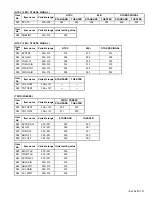
Страница 33: ...name Variable range Initial setting value AV 48WP55 AV 56WP55 AV 65WP55 A01 IN LEVEL 000 015 008 008 008 A02 LOW SEP 000 063 035 035 035 A03 HI SEP 000 063 020 020 020 A04 BBE BASS 128 127 010 010 010 A05 BBE TRE 128 127 000 000 000 A06 SURROUND 000 001 000 000 000 A07 BASS OFS 128 127 017 017 017 A08 TRE OFS 128 127 009 009 009 A09 AHS MVE 128 127 000 000 000 A10 AHS MSC 128 127 000 000 000 A11 N...

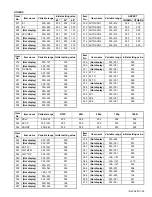
Страница 34: ...3 Not display 000 015 000 000 D14 H CENTER 000 255 117 117 D15 H FREQ 000 255 190 190 D16 Not display 000 127 100 100 D17 Not display 000 003 000 000 D18 Not display 000 001 000 000 D19 Not display 000 001 000 000 D20 Not display 000 001 000 000 D21 Not display 000 001 000 000 D22 Not display 000 001 000 000 D23 Not display 000 001 000 000 D24 Not display 000 001 000 000 D25 Not display 000 001 00...

Страница 35: ...o Item name Variable range 720p 1080i STANDARD THEATER 48 56 65 48 56 65 S03 BRIGHT 000 255 127 130 130 123 125 125 S04 CONTRAST 000 127 056 066 066 044 046 046 Item No Item name Variable range NTSC 480i STANDARD THEATER STANDARD THEATER 48 56 65 48 56 65 48 56 65 48 56 65 S05 0 MTX SW 000 003 000 000 000 000 000 000 000 000 000 000 000 000 S06 INPUT SW 000 003 001 001 001 001 001 001 001 001 001 ...

Страница 36: ...STANDARD THEATER HIGH LOW HIGH LOW HIGH LOW HIGH LOW 48 56 65 S10 DRIVE R 000 255 084 074 074 S11 Not display 128 127 003 000 000 001 005 005 008 S12 DRIVE B 000 255 078 083 083 S13 Not display 128 127 007 000 005 021 005 001 009 Item No Item name Variable range NTSC 480i 480p 720p 1080i STANDARD THEATER STANDARD THEATER STANDARD THEATER S14 CUTOF R 000 255 185 185 185 S15 Not display 128 127 004 ...

Страница 37: ...9 YWD STRT 000 015 002 000 000 S30 YWD GAIN 000 015 005 002 003 Item No Item name Variable range STANDARD THEATER S31 COL OFST 128 127 S32 TNT OFST 128 127 Item No Item name Variable range TWIN FREEZE STANDARD THEATER S33 BRT OFST 128 127 002 000 S34 CNT OFST 128 127 011 000 Item No Item name Variable range STANDARD THEATER S35 DCTRN SW 000 001 000 000 S36 BL OFF 000 001 000 001 S37 YGM OFF 000 00...

Страница 38: ...MID 128 127 015 S65 VM HIGH 128 127 010 S66 VM L 128 127 004 S67 VM LH 128 127 002 S68 VM MH 128 127 000 S69 VM M 128 127 001 S70 BLK R 000 001 000 S71 BLK G 000 001 000 S72 BLK B 000 001 000 S73 Not display 000 001 000 S74 Not display 000 001 000 S75 Not display 000 001 000 S76 Not display 000 001 000 S77 Not display 000 001 000 S78 Not display 000 001 000 S79 Not display 000 001 000 S80 Not disp...

Страница 39: ...00 001 000 F32 ATT V 000 001 000 F33 ATT U 000 001 000 F34 ATT C 000 001 000 F35 Not display 000 001 000 F36 Not display 000 001 000 F37 Not display 000 001 000 F38 DC1 000 001 000 F39 DC4 000 001 000 F40 DC5 000 001 000 Item No Item name Variable range Initial setting value Item No Item name Variable range NTSC 480i 480p 720p 1080i F41 SS LV 000 003 000 002 002 002 002 F42 SS CP 000 001 000 000 0...

Страница 40: ... 000 001 001 YCM037 Not display 000 003 001 YCM038 Not display 000 127 062 YCM039 Not display 000 127 073 YCM040 Not display 000 003 002 YCM041 Not display 000 063 016 YCM042 Not display 000 001 000 YCM043 Not display 000 001 000 YCM044 Not display 000 255 241 YCM045 Not display 000 001 000 YCM046 Not display 000 255 165 YCM047 Not display 000 001 001 YCM048 Not display 000 001 001 YCM049 Not disp...

Страница 41: ...ot display 000 001 001 YCM129 Not display 000 001 001 Item No Item name Variable range Initial setting value YCM130 Not display 000 003 001 YCM131 Not display 000 255 050 YCM132 Not display 000 255 154 YCM133 Not display 000 255 055 YCM134 Not display 000 007 001 YCM135 Not display 000 255 136 YCM136 Not display 000 001 000 YCM137 Not display 000 001 001 YCM138 Not display 000 007 003 YCM139 Not d...

Страница 42: ...isplay 000 001 000 YCS032 Not display 000 003 003 Item No Item name Variable range Initial setting value YCS033 Not display 000 001 001 YCS034 Not display 000 001 000 YCS035 Not display 000 255 096 YCS036 Not display 000 001 001 YCS037 Not display 000 003 001 YCS038 Not display 000 127 062 YCS039 Not display 000 127 073 YCS040 Not display 000 003 002 YCS041 Not display 000 063 016 YCS042 Not displ...

Страница 43: ... 000 001 000 YCS110 Not display 000 003 001 YCS111 Not display 000 003 001 YCS112 Not display 000 003 001 YCS113 Not display 000 003 001 YCS114 Not display 000 255 000 Item No Item name Variable range Initial setting value INPUT SIGNAL NTSC ASPECT FULL MULTI SINGLE VIDEO STATUS STANDARD COLOR TEMPERATURE LOW Item No Item name Variable range Initial setting value BR Not display 000 255 118 DRV R No...

Страница 44: ...AT 0 15 1 CBA34 CURS SPACE 0 7 1 CBA35 HATCH COL 0 7 2 CBA36 BORDER COL 0 7 0 CBA37 CURSOL COL 0 7 0 CBA38 CROSS COL 0 7 0 CBA39 SQUARE COL 0 7 0 CBA40 XCPOS VPOS 0 31 16 CBA41 XCPOS HPOS 0 31 16 CBA42 CURSOL PAT 0 3 0 CBA43 MTPH1 32768 32767 0 CBA44 MTPH2 32768 32767 0 CBA45 MTPV1 32768 32767 0 CBA46 MTPV2 32768 32767 0 CBA47 YSP 7 7 0 CBA48 BL1POSV 0 2047 0 CBA49 BL1POSH 0 4095 0 CBA50 BL2POSV 0...

Страница 45: ...021 Not display 000 00F 016 IPA022 Not display 000 0FF 023 IPA023 Not display 000 00F 000 Item No Item name Variable range Initial setting value IPA024 Not display 000 001 001 IPA025 Not display 000 001 001 IPA026 Not display 000 03F 01F IPA027 Not display 000 003 000 IPA028 Not display 000 03F 008 IPA029 Not display 000 03F 02B IPA030 Not display 000 00F 005 IPA031 Not display 000 007 001 IPA032 ...

Страница 46: ...012 DSB003 Not display Not display 02E DSB004 Not display Not display 000 DSB005 Not display Not display 000 DSB006 Not display Not display 001 DSB007 Not display Not display 011 DSB008 Not display Not display 001 DSB009 Not display Not display 010 DSB010 Not display Not display 001 DSB011 Not display Not display 001 DSB012 Not display Not display 008 DSB013 Not display Not display 012 DSB014 Not ...

Страница 47: ...C030 Not display 000 0FF 040 DSC031 Not display 000 00F 000 DSC032 Not display 000 0FF 0C0 DSC033 Not display 000 00F 000 DSC034 Not display 000 0FF 080 DSC035 Not display 000 00F 000 Item No Item name Variable range Initial setting value DSC036 Not display 000 0FF 040 DSC037 Not display 000 00F 005 DSC038 Not display 000 0FF 040 DSC039 Not display 000 00F 000 DSC040 Not display 000 0FF 0C0 DSC041...

Страница 48: ... Not display 000 001 000 Item No Item name Variable range Initial setting value HDM054 Not display 000 001 000 HDM055 Not display 000 001 000 HDM056 Not display 000 001 000 HDM057 Not display 000 001 001 HDM058 Not display 000 001 000 HDM059 Not display 000 001 001 HDM060 Not display 000 001 000 HDM061 Not display 000 001 001 HDM062 Not display 000 001 001 HDM063 Not display 000 001 000 HDM064 Not...

Страница 49: ...ay Not display 002 RHD061 Not display Not display 000 Item No Item name Variable range Initial setting value RHD062 Not display Not display 000 RHD063 Not display Not display 000 RHD064 Not display Not display 000 RHD065 Not display Not display 000 RHD066 Not display Not display 000 RHD067 Not display Not display 000 RHD068 Not display Not display 000 RHD069 Not display Not display 000 RHD070 Not ...

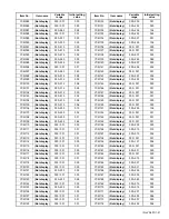
Страница 50: ...y Not display 000 RHD138 Not display Not display 000 RHD139 Not display Not display 000 RHD140 Not display Not display 000 RHD141 Not display Not display 000 RHD142 Not display Not display 000 RHD143 Not display Not display 000 RHD144 Not display Not display 000 RHD145 Not display Not display 000 RHD146 Not display Not display 000 RHD147 Not display Not display 000 RHD148 Not display Not display 0...

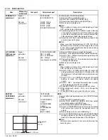
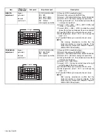
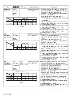
Страница 51: ...t part Description H FREQUENCY adjustment Signal generator Remote control unit 1 PICTURE SOUND D15 H FREQ D18 DEF RST 1 Receive NTSC crosshatch signal 2 Select FULL mode with ASPECT key 3 Select 1 PICTURE SOUND from SERVICE MENU 4 Select D18 DEF RST and change the data 0 to 1 free run 5 While observing the screen adjust the D15 H FREQ so that an optimum horizontal synchronization is obtained see f...

Страница 52: ...us in the top and the bottom on either side in the diagonal When the difference of the focus is big it removes a main lens and it puts a washer between the main lens and the coupler and adjusts it BEAM SPOT 5 Change dot pattern with INPUT key 6 Makes a red single color 7 Turn the R FOCUS VR clockwise from just focus point to set the dot diameter approx to Ø30mm 8 Turn the 4 pole magnet of the proj...

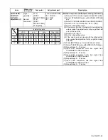
Страница 53: ...ct 1 PICTURE SOUND and change the data in the setting item F62 from 0 to 1 For details please refer to the adjustment of DEFLECTION As a result you can get the screen as shown in bellow figure Adjust the DEFLECTION circuit in order of the steps indicated by the downward arrows NOTE When every adjustment of the DEFLECTION circuit has completed start the adjustment of convergence PREPARATION DEFLECT...

Страница 54: ...the data 0 to 1 then it makes picture without convergence operation 5 Makes a green single color NOTE When making a single color while adjusting of one CRT put the cap on other lens 6 Select D03 H SIZE and shorten the level until and perpendicular amplitude of vibration with until the blanking in Left and Right and on either side can be seen 7 Select D14 H CENTER and adjust horizontal position to ...

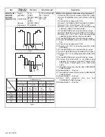
Страница 55: ...unit 1 PICTURE SOUND D14 H CENTER F62 Without convergence operation 1 Receive NTSC circle pattern signal 2 Select FULL mode with ASPECT key 3 Select 1 PICTURE SOUND from SERVICE MENU 4 Select F62 Without convergence operation 5 Change the data 0 to 1 then it makes picture without convergence operation 6 Select D14 H CENTER 7 Adjust D14 to make D E as shown figure 8 Press MUTING key to memorize the...

Страница 56: ... adjusted If the horizontal is out of alignment readjust it Adjust H SIZE SIDE PIN reparably TRAPEZIUM adjustment Signal generator Remote control unit 1 PICTURE SOUND D07 EW TRAP F62 Without convergence operation 1 Receive NTSC crosshatch signal 2 Select FULL mode with ASPECT key 3 Select 1 PICTURE SOUND from SERVICE MENU 4 Select F62 Without convergence operation 5 Change the data 0 to 1 then it ...

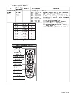
Страница 57: ...l 2 Select 6 CONVER A from SERVICE MENU 3 Select CPA item with INPUT key 4 Check and set data that CPA04 CPA11 are same value as table1 5 Press MUTING key to memorize the set values CPA04 TPOV OFST 0 Item name Item No Initial setting value CPA05 FINEP 1245 CPA06 STARTLIN A 56 CPA07 STARTLIN B 1 CPA08 CAU H2 0 CPA09 COARS OFST 50 CPA10 V1OFSTA 7 CPA11 V1OFSTB 0 REMOTE CONTROL KEY POSITION CPA CCA C...

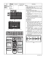
Страница 58: ...o1 Clear the fine adjustment data 5 Select CCA item with INPUT key Then a green crosshatch pattern for adjustment will be displayed on the screen 6 Check and set data CCA01 CCA11 are same value as table2 7 Press SELECT key to change the adjusting color to red and blue NOTE Press OK key to change the display colors Whenever OK key is pressed the menu will sequence in this order Two colors adjusting...

Страница 59: ...djustments so that they align with the adjusting points of the green crosshatch pattern reference color 11 Press OK key to change the display colors to three colors from two colors adjusting color green and make sure that the convergence has been aligned with each other 12 Press MUTING key to memorize the set values Fig 3 Fig 1 Fig 2 Item Measuring instrument Test point Adjustment part Description...

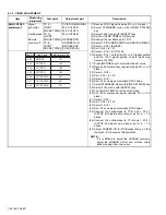
Страница 60: ...emorize the set value 12 Receive 480i component signal include 0 or 3 black 13 Select S03 14 Set S03 to 127 15 Select S16 16 Set S16 same as memorized NTSC value 17 Select STANDARD mode with VIDEO STATUS key 18 Select FULL mode with ASPECT key 19 The COLOR TEMP set at the LOW mode 20 Set 1080i component signal include 0 or 3 black 21 Select S03 22 Set S03 to 127 23 Select S16 24 Set S16 same as me...

Страница 61: ... 3 WHITE BALANCE CUT R value was changed from 215 to 210 1 PICTURE SOUND S03 value was changed from 185 to 180 automatically WHITE BALANCE HIGH LIGHT adjustment Signal generator Remote control unit 1 PICTURE SOUND S10 DRIVE R S12 DRIVE B 3 WHITE BALANCE DRV R DRV B 1 Receive NTSC grayscale signal include 75 white 2 Select STANDARD mode with VIDEO STATUS key 3 Set the COLOR TEMP is LOW mode 4 Selec...

Страница 62: ...es 9 Select THEATER mode with VIDEO STATUS key 10 Repeat steps 4 8 above 11 Input 480i component black white signal from COMPONENT VIDEO terminal 12 Repeat steps 2 10 above 13 Receive 1080i component black white signal from COMPONENT VIDEO terminal 14 Repeat steps 2 10 above SUB CONTRAST adjustment 2 Signal generator Oscilloscope Remote control unit TP G G CRT SOCKET PWB 1 PICTURE SOUND S04 CONTRA...

Страница 63: ...f the color bar is not clearly with the initial setting value make fine adjustment until you get the clearly color bar 10 Press MUTING key to memorize the set value 11 Select THEATER mode with VIDEO STATUS key 12 Repeat steps 3 10 above 13 Input 480i component color bar signal from COMPONENT VIDEO terminal 14 Repeat steps 2 12 above 15 Input 480p component color bar signal from COMPONENT VIDEO ter...

Страница 64: ...oscilloscope to TP B 13 Adjust S07 B Y to be setting value C V Refer to the table 14 Press MUTING key to memorize the set values 15 Select THEATER mode with VIDEO STATUS key 16 Adjust S07 to be setting value D V Refer to the table 17 Press MUTING key to memorize the set values 18 Confirm that LOW LIGHT is not different after adjusting If it is green or magenta to adjust LOW LIGHT again If adjust a...

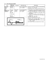
Страница 65: ... SEP A03 HI SEP 1 Input stereo L signal 300Hz from the TV audio multiplex signal generator to the antenna terminal 2 Connect an oscilloscope to L OUTPUT pin of the AUDIO OUT and display one cycle portion of the 300Hz signal 3 Change the connection of the oscilloscope to R OUTPUT pin of the AUDIO OUT and enlarge the voltage axis 4 Select A02 LOW SEP 5 Set the initial setting value of A02 6 Adjust A...

Страница 66: ... 9 failures are stored on the record the counter remains stopped at 9 SYNC is neither counted nor stored in memory Because of the timing of Vcc start up and shut down of the IC connecting to the I2C bus during which the power is turned on and off the operation may be interpreted as an error In order to avoid the misinterpretation the self check functions should be started at about 3 seconds after ...

Страница 67: ...ared NG is shown MEM Memory EEP ROM ACK is returned when I2C traffic is carried out IC1703 MEMORY MI COM DIST MODULE PWB The state is monitored every time when I2C traffic is carried out Then the state is counted as a failure if ACK is not returned AVSW AV switch Ditto IC1301 AN15852A and IC1501 CXA2069Q MAIN PWB Ditto VCD Video process RGB process Ditto IC1301 AN15394A MI COM DIST MODULE PWB Ditt...

Страница 68: ...1 68 No YA097 ...
Страница 69: ...7 WPC Printed in Japan JVC SERVICE ENGINEERING COMPANY OF AMERICA DIVISION OF JVC AMERICAS CORP www jvcservice com US Only JVC CANADA INC Head office 21 Finchdene Square Scarborough Ontario M1X 1A7 416 293 1311 ...

Отзывы: