


STRM Series II Hardware Installation Guide
Installing the Flow Collector 4-port LAN Card on STRM 500 II
17
Installing the Flow
Collector 4-port
LAN Card on STRM
500 II
The Flow Collector collects data from devices and various live and recorded feeds
such as network taps, span/mirror ports, NetFlow, and STRM flow logs. The Flow
Collector then groups related individual packets into a flow. A flow starts when the Flow
Collector detects the first packet with a unique source IP address, destination IP
address, source port, and destination port as well as other specific protocol options,
which may determine the start of a communication. Each additional packet is
evaluated and counts of bytes and packets are added to the statistical counters in the
flow record. At the end of an interval a status record of the flow is sent to a Flow
Processor and statistical counters for the flow are reset. A flow ends when no activity
for the flow is seen within the configured period of time. Flow reporting generates
records of all the active or expired flows during a specified period of time. STRM
defines these flows as a communication sessionbetween two pairs of unique IP
address/ports that use the same protocol. If the protocol does not support port-based
connections, STRM combines all packets between the two hosts into a single flow
record. However, a Flow Collector does not record flows until a connection is made to
another STRM component and data is retrieved.
To install the Flow Collector 4-port LAN card on an STRM 500 II unit:
Step 1
Power down the STRM 500 II unit.
Step 2
Unscrew the two thumbscrews on the right-most blank IO module and remove the
dummy tray.
Step 3
Insert the 4-port 1GB LAN module firmly and screw in the two thumbscrews.
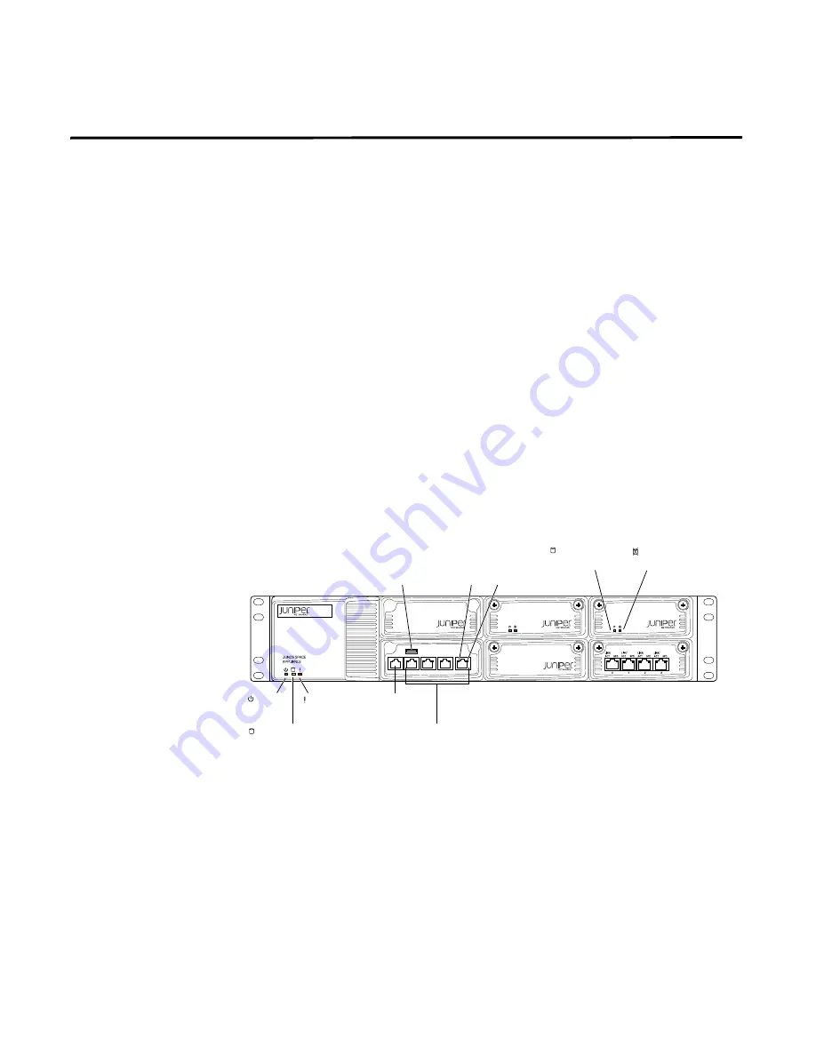
Figure 10 STRM 500 II with the Flow Collector 4-port LAN card inserted
Step 4
Power on the STRM 500 II unit and watch it boot on the serial console.
Step 5
Verify the link and activity LED on the new 4-port 1GB LAN module light up when
connecting the ports to your Ethernet switch with a standard CAT5e or CAT6 LAN
cable.
Step 6
Login to the admin console and you should now see 4 more Ethernet interfaces appear
as eth4-eth7. The 4-port are labeled 0, 1, 2 and 3 and should map to Ethernet
interfaces as follows:
- 0 = eth7
- 1 = eth6
- 2 = eth5
Console
port
STRM 500
Eth 1
Eth 0
Drive 0
Drive 1
g040038
CONSOLE
ETH3
ETH2
ETH1
ETH0
g040405
Power
LED
Hardware
LED
Hard disk LED
Network ports
Console
port
Left
LAN
LED
Right
LAN
LED
STRM 500 II
Hard disk
Activity LED
Hard disk
Failure LED
USB
maintenance
port
Содержание STRM 2500
Страница 6: ......
Страница 12: ...STRM Series II Hardware Installation Guide 4 STRM OVERVIEW...
Страница 32: ...STRM Series II Hardware Installation Guide 24 PREPARING YOUR SYSTEM FOR STRM SOFTWARE INSTALATION...
Страница 48: ...STRM Series II Hardware Installation Guide 40 RACK MOUNTING THE STRM SERIES II APPLIANCE...


