background image

• Electrostatic discharge (ESD) grounding strap

• Replacement fan

• A Phillips (+) screwdriver, number 1 or 2 (optional), for the captive screw

CAUTION: Do not remove a fan unless you have a replacement fan available.

To remove an SSR1300 fan:

1. Wrap and fasten one end of the ESD grounding strap around your bare wrist, and connect the other

end of the strap to one of the ESD points on the chassis.

2. Loosen the captive screw with a Phillips screwdriver or by unscrewing the screws with your thumb

and forefinger.

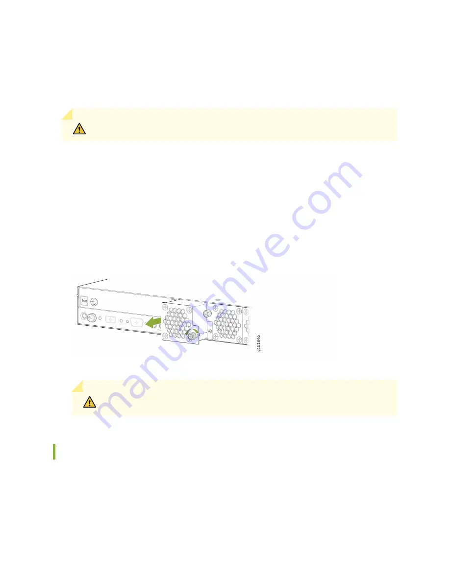
3. Grasp the captive screw and pull the fan completely out of the chassis. See 

Figure 17 on page 46

.

Figure 17: Remove an SSR1300 Fan

4. Place the fan in the antistatic bag or on the antistatic mat placed on a flat, stable surface.

CAUTION: Replace a fan immediately to avoid chassis overheating.

Install a Fan in the SSR1300

Before you begin to install a fan:

• Ensure that you understand how to prevent ESD damage.

• Ensure that you have the following parts and tools available:

46

Содержание SSR1300

Страница 1: ...SSR1300 Appliance Hardware Guide Published 2022 08 30...

Страница 2: ...Guide Copyright 2022 Juniper Networks Inc All rights reserved The information in this document is current as of the date on the title page YEAR 2000 NOTICE Juniper Networks hardware and software produ...

Страница 3: ...ystem 9 Power System 10 2 Site Planning Preparation and Specifications Site Preparation Checklist for SSR1300 15 SSR1300 Site Guidelines and Requirements 16 General Site Installation Guidelines 17 Sit...

Страница 4: ...ing Components Maintaining the SSR1300 Hardware Components 45 SSR1300 Fan Maintenance 45 Remove a Fan from the SSR1300 45 Install a Fan in the SSR1300 46 SSR1300 Power Supply Maintenance 47 Replacing...

Страница 5: ...vention of Electrostatic Discharge Damage 63 Fire Safety Requirements 64 Laser and LED Safety Guidelines and Warnings 66 Chassis and Component Lifting Guidelines 69 Radiation from Open Port Apertures...

Страница 6: ...onfiguration routine maintenance and troubleshooting for the SSR1300 appliance After completing the installation and basic configuration procedures covered in this guide refer to the Session Smart Rou...

Страница 7: ...1 CHAPTER Overview SSR1300 Appliance Overview 2 SSR1300 Chassis 3...

Страница 8: ...n traffic Applications devices or users cannot initiate any session that does not comply with the authentication policies and access rules The SSR1300 supports Layer 2 through Layer 5 stateful firewal...

Страница 9: ...t pluggable You can remove and replace these components without powering off the appliance but the appliance function is interrupted until you replace the component The FRUs in SSR1300 appliances are...

Страница 10: ...1 GbE Ethernet ports 1 0 through 1 3 2 RJ 45 Console port 7 Micro USB Console port 3 10 GbE SFP ports 0 0 through 0 3 8 USB 3 0 ports 4 1 GbE management port for Mist operations 9 RESET button 5 1 10...

Страница 11: ...sical specifications of SSR1300 Table 1 Physical Specifications of SSR1300 Model Height Width Depth Weight SSR1300 44 mm 438 mm 650 mm 19 2 kg 42 33 lbs Chassis Status LEDs Figure 3 on page 5 shows th...

Страница 12: ...es a major alarm such as a hardware component failure Off The device is not receiving power 3 SSD Blinking amber Indicates SSD activity Off There is no SSD activity Network Port LEDs Each network port...

Страница 13: ...ity on the port Solid green Link is established but there is no activity on the port Off There is no link established 2 Speed Solid green The link is operating at 10 Gbps speed Figure 5 on page 7 show...

Страница 14: ...but there is no activity on the port Off There is no link established 2 Speed LED on the right Solid amber The link is operating at 1 Gbps speed Solid green The link is operating at 100 Mbps speed Off...

Страница 15: ...The link is operating at 10 Gbps speed Off The link is operating at 1 Gbps speed Cooling System The cooling system of the SSR1300 consists of four fans which are hot insertable and hot removable field...

Страница 16: ...nit FRU when the second power supply is installed and running You can remove and replace either one of them without powering off the appliance or disrupting the appliance functions NOTE If both power...

Страница 17: ...n IEC standard 60320 The plug end of the power cord fits into the power source outlet that is standard for your geographical location Table 7 on page 11 lists the AC power cords specifications provide...

Страница 18: ...R C13 CH Europe except Italy Switzerland and United Kingdom 250 VAC 10 A 50 Hz CEE 7 VII Type VIIG CBL EX PWR C13 EU India 250 VAC 10 A 50 Hz IS 1293 Type IND 3 CBL EX PWR C13 IN No graphic available...

Страница 19: ...Hz or 60 Hz CEE 7 VII Type VIIGK CBL EX PWR C13 KR North America 125 VAC 13 A 60 Hz NEMA 5 15 Type N5 15 CBL EX PWR C13 US South Africa 250 VAC 10 A 50 Hz SABS 164 1 1992 Type ZA 3 CBL EX PWR C13 SA S...

Страница 20: ...2 CHAPTER Site Planning Preparation and Specifications Site Preparation Checklist for SSR1300 15 SSR1300 Site Guidelines and Requirements 16 Cable Specifications and Pinouts for SSR1300 23...

Страница 21: ...environmental factors such as temperature and humidity do not exceed device tolerances Environmental Requirements and Specifications for SSR1300 on page 19 Power Measure the distance between the exte...

Страница 22: ...e Cables Acquire cables and connectors Review the maximum distance allowed for each cable Choose the length of cable based on the distance between the hardware components being connected Plan the cabl...

Страница 23: ...e appliance Follow the ESD procedures to avoid damaging equipment Static discharge can cause components to fail completely or intermittently over time Install the appliance in a secure area so that on...

Страница 24: ...e To reduce or eliminate RFI from your site wiring do the following Use a twisted pair cable with a good distribution of grounding conductors If you must exceed the recommended distances use a high qu...

Страница 25: ...158 F Clearance Requirements for Hardware Maintenance of SSR1300 When planning the site for installing an SSR1300 you must allow sufficient clearance around the installed chassis For the operating te...

Страница 26: ...ts for SSR1300 You can mount the SSR1300 on four post racks The rack mounting kit is shipped with the device You can order a spare rack mounting kit part number JNP RMK SSRHE separately if required Ta...

Страница 27: ...and strength requirements to support the weight A U is the standard rack unit defined in Cabinets Racks Panels and Associated Equipment document number EIA 310 D published by the Electronics Industry...

Страница 28: ...the rails in a rack that complies with this standard is usually wider than the device s mounting brackets which measure 19 in 48 26 cm from outer edge to outer edge Use approved wing devices to narro...

Страница 29: ...vice by using the Hardware Compatibility Tool The tool also documents the optical and cable characteristics where applicable for each transceiver You can search for transceivers by product and the too...

Страница 30: ...3 CHAPTER Initial Installation and Configuration Unpack and Mount an SSR1300 25 Connect SSR1300 to Power 30 Connect SSR1300 to External Devices 34 Onboarding SSR Conductor Managed SSR1300 onto Mist 35...

Страница 31: ...number 2 A box cutter or packing knife to slice open the tape that seals the boxes Unpack an SSR1300 The SSR1300 is shipped in a cardboard carton and secured with foam packing material NOTE The SSR130...

Страница 32: ...d on the configuration you order If any part on the packing list is missing contact your customer service representative or contact Juniper customer care from within the U S or Canada by telephone at...

Страница 33: ...appliance into a four post rack or a cabinet Complete these prerequisites before you install the appliance Prepare the site for installation as described in Site Preparation Checklist for SSR1300 on p...

Страница 34: ...d Warnings 2 Wrap and fasten one end of the electrostatic discharge ESD cable grounding strap around your bare wrist and connect the other end to a site ESD point 3 Remove the SSR1300 from the shippin...

Страница 35: ...the screws in the two bottom holes first and then tighten the screws in the two top holes next Figure 10 Install the SSR1300 Appliance in a Four Post Rack 8 Continue to support the SSR1300 in place an...

Страница 36: ...onal injury IN THIS SECTION Connect Earth Ground to SSR1300 30 Connect Power to SSR1300 32 Power Off the SSR1300 33 NOTE To meet safety and electromagnetic interference EMI requirements and to ensure...

Страница 37: ...ance To ground the appliance 1 Wrap and fasten one end of the ESD grounding strap around your wrist and connect the other end to a site ESD point For more details see Prevention of Electrostatic Disch...

Страница 38: ...and to ensure proper operation you must connect the chassis to an earth ground before you connect it to power For installations that require a separate grounding conductor to the chassis use the prot...

Страница 39: ...33 Figure 14 Connect AC Power Cord 6 Repeat step 4 and step 5 to insert the second power cord 7 If the AC power source outlet has a power switch set it to the off O position 8 Insert the power cord pl...

Страница 40: ...r switch while the appliance is shutting down To remove power completely from the appliance unplug the power cord or switch off the power source After powering off a power supply wait at least 10 seco...

Страница 41: ...console server see Figure 15 on page 35 or management console see Figure 16 on page 35 Figure 15 Connecting the SSR1300 to a Management Console through a Console Server Figure 16 Connecting the SSR13...

Страница 42: ...ions For Apple Devices For Android Devices Pre Onboarding Verification When onboarding a conductor managed appliance the process is simplified by ensuring that the IP address of the managing conductor...

Страница 43: ...present use the SSR GUI to copy the IP address 4 On the Configuration Home panel in the SSR GUI click Authority 5 Under Authority Settings scroll down to Conductor Addresses and copy the IP address o...

Страница 44: ...6 Return to the Mist Site Configuration scroll down to the Session Smart Conductor and add the Conductor IP address 38...

Страница 45: ...ocess to onboard a conductor managed SSR device into the Mist cloud using the Mist UI and your Claim Code 1 Unbox the SSR1300 appliance 2 Connect to the WAN port The port 0 0 on the front panel of the...

Страница 46: ...e the claim code is 427YYQFLKKV6F8N 5 Login to the Mist UI on another device and navigate to your organization 6 Go to the WAN Edges page and click Claim WAN Edges 7 Enter the Claim Code NOTE Under Ma...

Страница 47: ...te configuration After a few minutes the SSR will appear in the inventory as Unassigned Once it appears in the inventory it must be assigned to a site Assign the SSR1300 appliance to a site to complet...

Страница 48: ...list select Assign to Site 2 Select the site from the Site list Under Manage Configuration do not check Manage Configuration with Mist for the SSR Conductor managed appliance This allows the device t...

Страница 49: ...t Router software version 6 0 If Manage Configuration with Mist is not selected the appliance will not be managed by Mist 3 Click Assign to Site The site assignment will take a few minutes Once the si...

Страница 50: ...4 CHAPTER Maintaining Components Maintaining the SSR1300 Hardware Components 45 SSR1300 Fan Maintenance 45 SSR1300 Power Supply Maintenance 47 Unmount the SSR1300 Chassis 50...

Страница 51: ...ponents on page 53 SSR1300 Fan Maintenance SUMMARY Maintaining the SSR1300 includes removing and installing the fans IN THIS SECTION Remove a Fan from the SSR1300 45 Install a Fan in the SSR1300 46 Th...

Страница 52: ...2 Loosen the captive screw with a Phillips screwdriver or by unscrewing the screws with your thumb and forefinger 3 Grasp the captive screw and pull the fan completely out of the chassis See Figure 17...

Страница 53: ...bottom of the fan with the bottom of the fan slot 3 Rest the bottom edge of the fan in the slot and slide the fan into place so it is fully seated 4 Tighten the captive screw until it is finger tight...

Страница 54: ...supply Removing the AC Power Supply from an SSR1300 To remove a power supply from the appliance see Figure 19 on page 49 1 If the AC power source outlet has a power switch set it to the off 0 position...

Страница 55: ...e antistatic mat placed on a flat stable surface Installing the AC Power Supply in an SSR1300 To install an AC power supply see Figure 20 on page 50 1 Attach the ESD grounding strap to your bare wrist...

Страница 56: ...hassis Figure 20 Install an SSR1300 AC Power Supply 5 Connect the power cord see Connect SSR1300 to Power on page 30 Unmount the SSR1300 Chassis IN THIS SECTION Remove the SSR1300 from a Rack 50 Remov...

Страница 57: ...any cables or wires attached to the SSR1300 To remove an SSR1300 from a rack 1 Have one person support the weight of the appliance while another person uses the screwdriver to remove the front mountin...

Страница 58: ...5 CHAPTER Contacting Customer Support and Returning the Chassis or Components Contacting Customer Support and Returning the Chassis or Components 53...

Страница 59: ...n a Hardware Component to Juniper Networks Inc If a hardware component fails please contact Juniper Networks Inc to obtain a Return Material Authorization RMA number This number is used to track the r...

Страница 60: ...er and serial number of the defective component 2 Obtain an RMA number from the JTAC You can send e mail or contact JTAC by telephone as described above 3 Provide the following information in your e m...

Страница 61: ...Assistance Center JTAC After locating the serial number of the device or component you want to return open a service request with JTAC on the Web or by telephone Before you request an RMA from JTAC b...

Страница 62: ...t and issues an RMA number for return of the component Guidelines for Packing and Shipping Hardware Components To pack and ship individual components 1 When you return the chassis or components make s...

Страница 63: ...equirements 64 Laser and LED Safety Guidelines and Warnings 66 Chassis and Component Lifting Guidelines 69 Radiation from Open Port Apertures Warning 69 Maintenance and Operational Safety Guidelines a...

Страница 64: ...andard practices for preventing accidents Waarschuwing Dit waarschuwingssymbool betekent gevaar U verkeert in een situatie die lichamelijk letsel kan veroorzaken Voordat u aan enige apparatuur gaat we...

Страница 65: ...lo de aviso significa peligro Existe riesgo para su integridad f sica Antes de manipular cualquier equipo considerar los riesgos que entra a la corriente el ctrica y familiarizarse con los procedimien...

Страница 66: ...ructions are provided in the hardware documentation for this device Such an action could cause severe electrical shock Do not push or force any objects through any opening in the chassis frame Such an...

Страница 67: ...s zones auxquelles seul le personnel de service peut acc der en utilisant un outil sp cial un m canisme de verrouillage et une cl ou tout autre moyen de s curit L acc s aux zones de s curit est sous l...

Страница 68: ...dning och kontrolleras av den auktoritet som ansvarar f r omr det Qualified Personnel Warning WARNING Only trained and qualified personnel should install or replace the device Waarschuwing Installatie...

Страница 69: ...d make sure that it is in direct contact with your skin If a grounding strap is not available hold the component in its antistatic bag see Figure 22 on page 64 in one hand and touch the exposed bare m...

Страница 70: ...tistatic Bag CAUTION ANSI TIA EIA 568 cables such as Category 5e and Category 6 can get electrostatically charged To dissipate this charge always ground the cables to a suitable and safe earth ground...

Страница 71: ...hich uses noncorrosive fire retardants to extinguish the fire Fire Suppression Equipment Type C fire extinguishers which use noncorrosive fire retardants such as carbon dioxide and Halotron are most e...

Страница 72: ...t Warning 67 Class 1 LED Product Warning 67 Laser Beam Warning 68 Juniper Networks devices are equipped with laser transmitters which are considered a Class 1 Laser Product by the U S Food and Drug Ad...

Страница 73: ...u laser sur la r tine toute focalisation directe de l il sur une source laser m me de faible puissance peut entra ner des l sions oculaires irr versibles Class 1 Laser Product Warning LASER WARNING Cl...

Страница 74: ...reeks bekijken met optische instrumenten Varoitus l katso s teeseen l k tarkastele sit suoraan optisen laitteen avulla Avertissement Ne pas fixer le faisceau des yeux ni l observer directement l aide...

Страница 75: ...39 7 lb 18 kg to 70 5 lb 32 kg Two or more people 70 5 lb 32 kg to 121 2 lb 55 kg Three or more people Above 121 2 lb 55 kg Use material handling systems such as levers slings lifts and so on When thi...

Страница 76: ...tr ling kan emiteres fra portens pning n r det ikke er tilkoblet en fiberkabel Aviso Dada a possibilidade de emiss o de radia o invis vel atrav s do orif cio da via de acesso quando esta n o tiver nen...

Страница 77: ...pas remplac e correctement Ne la remplacer que par une pile de type semblable ou quivalent recommand e par le fabricant Jeter les piles usag es conform ment aux instructions du fabricant Warnung Bei...

Страница 78: ...dwonden veroorzaken of het metalen voorwerp aan de aansluitklemmen lassen Varoitus Ennen kuin ty skentelet voimavirtajohtoihin kytkettyjen laitteiden parissa ota pois kaikki korut sormukset kaulakorut...

Страница 79: ...es y relojes Los objetos de metal se calientan cuando se conectan a la alimentaci n y a tierra lo que puede ocasionar quemaduras graves o que los objetos met licos queden soldados a los bornes Varning...

Страница 80: ...er Networks router dan ook oververhit raakt dient u deze niet te bedienen op een plaats waar de maximale aanbevolen omgevingstemperatuur van 40 C wordt overschreden Om te voorkomen dat de luchtstroom...

Страница 81: ...deixe pelo menos um espa o de 15 2 cm volta das aberturas de ventila o Atenci n Para impedir que un encaminador de la serie Juniper Networks switch se recaliente no lo haga funcionar en un rea en la...

Страница 82: ...este producto debe realizarse seg n todas las leyes y regulaciones nacionales Varning Slutlig kassering av denna produkt b r sk tas i enlighet med landets alla lagar och f reskrifter Action to Take A...

Страница 83: ...non guardate direttamente nelle aperture Advarsel Unng utsettelse for str ling og stirr ikke inn i pninger som er pne fordi usynlig str ling kan emiteres fra portens pning n r det ikke er tilkoblet en...

Страница 84: ...caution suffisante pour raccorder physiquement ces interfaces au c blage de l installation ext rieure CAUTION Before removing or installing components of a device connect an electrostatic discharge E...

Страница 85: ...hin marked electrical ratings and product usage instructions To ensure that the device and peripheral equipment function safely and correctly use the cables and connectors specified for the attached p...

Страница 86: ...1000 Series KN 32 and KN 35 KN 61000 Series BSMI CNS 13438 TEC SD DD EMC 221 05 OCT 16 Environmental Reduction of hazardous Substances ROHS 6of6 with no exemptions 7a exemption for power supply compon...

Страница 87: ...only with the same or equivalent type Dispose used batteries according to the local laws and regulations regarding safe disposal of lithium batteries Disposal of a battery into a fire or by crushing o...

Отзывы: