background image

CHAPTER 7

General Safety Guidelines and Warnings

IN THIS CHAPTER

CTP Safety Guidelines and Warnings | 72

CTP Safety Guidelines and Warnings

For your safety, before installing the device, review all safety warnings in this section.

WARNING:

The recommended maximum ambient temperature is 40˚°C (104° F). For

safe operation take into consideration the internal temperature within the rack.

WARNING:

Install equipment in the rack from the bottom upward. Doing this helps

maintain the stability of the rack and reduces the chance of the rack tipping over.

WARNING:

Do not insert any metal object, such as a screwdriver, into an open slot

or the backplane. Doing so can cause electric shock and serious burns.

WARNING:

For the larger CTP series devices, three people are required to install the

device in a rack: two to lift the device into position and one to screw it to the rack.

WARNING:

Connect the device or rack to ground (earth), and ensure that a reliable

grounding path is maintained in the rack.

72

Содержание CTP2000 Series

Страница 1: ...CTP2000 Series Circuit to Packet Platforms Hardware Guide Published 2020 08 31 ...

Страница 2: ...er or otherwise revise this publication without notice CTP2000 Series Circuit to Packet Platforms Hardware Guide Copyright 2019 Juniper Networks Inc All rights reserved Revision History February 2017 Revision 2 January 2019 Revision 3 The information in this document is current as of the date on the title page END USER LICENSE AGREEMENT The Juniper Networks product that is the subject of this tech...

Страница 3: ...Module 13 CTP2000 4WE M Interface Module 14 Supervisory Signaling 18 CTP2000 2W FXS and 2W FXO Interface Modules 20 Required Cables and Pinouts 22 Analog FXS FXO Loop Start Signaling 22 Answer Supervision 22 Disconnect Supervision 22 Analog FXS FXO Ground Start Signaling 23 Digital Signaling 23 Digital FXS FXO Loop Start Signaling 23 Digital FXS FXO Ground Start Signaling 24 CTP2000 8P IRIG Interf...

Страница 4: ... 43 CTP2000 Rack Installation 43 CTP Cabling Recommendations 44 Cable and Pinout Specifications 45 CTP2000 4WE M Interface Connector Pinouts 45 CTP2000 4WE M RTM Connector A Pinouts 45 CTP2000 4WE M Connector B Pinouts 46 CTP2000 FXS and FXO Interface Module Cables and Pinouts 48 Required Cables 48 RTM Pinout Locations 48 FXS Connector Pinouts 49 FXO Connector Pinouts 50 T1 E1 Interface Module Pin...

Страница 5: ...d Industrie Canada 80 Canadian Department of Communications Explanatory Notes 81 DOC Explanatory Notes Equipment Attachment Limitations 81 Notes explicatives du ministère des Communications limites visant les accessoires 81 Statements of Volatility for Juniper Network Devices 82 Installation 4 Unpacking and Inspecting the CTP Platform 87 Before You Unpack the CTP Platform 87 Unpacking the CTP Devi...

Страница 6: ...oving SFPs in a CTP2000 Module 104 Upgrading Components for Memory Upgrades 106 Upgrading CTP2000 Series Components for Memory Upgrades 106 Cabling 108 Cabling the CTP2000 Platform Overview 108 Required Tools Wires and Cables for the CTP2000 Platform 109 CTP2000 Management Ports 110 Cabling a CTP2000 T1 E1 Interface Module 111 Cabling the CTP Platform for DC Power 111 Task 1 Turning Off All CTP Pl...

Страница 7: ...ng the CTP Platform 128 Replacing an AC Power Supply 129 Product Reclamation and Recycling 131 Product Reclamation and Recycling Program 131 Replacing Fan Trays 133 Removing a CTP2000 Fan Tray 133 Installing a CTP2000 Fan Tray 133 Packing and Returning Hardware 135 Return Procedure 135 Returning CTP Products for Repair or Replacement 136 Troubleshooting 7 Troubleshooting Power Failures 138 CTP Pla...

Страница 8: ...1 PART Overview CTP2000 Series Platform Overview 2 CTP2000 Series Interface Modules 11 ...

Страница 9: ... signal from the received packet flow at the other end CTP Series platforms provide compact and lightweight chassis high port density and multiple Ethernet interfaces Each CTP Series platform runs the CTP operating system CTPOS and can be managed by the Juniper Networks CTPView Network Management System The CTPView Network Management System is a secure Web based management tool for provisioning ma...

Страница 10: ... a 3 U high full rack wide chassis designed for tabletop or shelf installation It can also be installed in a rack with the supplied rack mounting kit The CTP2008 platform has one removable interface module and one removable processor module and is available in both AC powered and DC powered versions It has a removable fan tray and airflow is side to side Figure 2 on page 3 Figure 3 on page 4 and F...

Страница 11: ... IEC power cord for the AC version Use a 22 AWG fork terminal connector for the DC version There is no power redundancy for the AC version and the DC version There are no power switches on CTP2000 Series DC models so a readily accessible disconnect device must be provided as part of the electrical installation of the unit We recommend the 22 AWG wire for DC power terminals Ethernet connection Prov...

Страница 12: ...P2024 chassis containing the PP332 processor which requires an RTM card for Ethernet and console port accesses The new PP833 processor module does not require an RTM card All PP833 module access is located on the front panel with all CTP serial and T1 E1 ports If you are upgrading from the old PP310 or PP332 processor to the PP833 processor the RTM card may be left in the node But none of the inte...

Страница 13: ...terminal connector for the DC version Power redundancy is supported for the AC version and the DC version A single IEC power cord is used to connect the redundant AC power supply modules which keeps the chassis turned on in the event of failure of one of the power supplies There are no power switches on CTP2000 Series DC models so a readily accessible disconnect device must be provided as part of ...

Страница 14: ...processor module and is available in both AC powered and DC powered versions It has a removable fan tray and airflow is side to side Figure 8 on page 8 Figure 9 on page 9 and Figure 10 on page 10 show the CTP2056 chassis containing the PP332 processor which requires an RTM card for Ethernet and console port accesses The new PP833 processor module does not require an RTM card All PP833 module acces...

Страница 15: ...e 30 and Installing a PMC on CTP2000 Platforms on page 99 Power supply extractor Push the button to eject the power supply module Fan tray and air filter The rear panel RTM comprises the following components see Figure 9 on page 9 and Figure 10 on page 10 Clock module Provides clock distribution between modules when the backplane is in use by voice applications Power supply Use a standard IEC powe...

Страница 16: ...des an asynchronous tty connection for locally configuring the CTP Series device On the PP310 and PP332 processors you can connect a console directly to the COM2 port which is an RJ 45 type connector found on the RTM panel Figure 9 CTP2056 Platform Containing the PP332 Processor AC Version Rear View Interface module slot 1 Interface module slot 2 9 ...

Страница 17: ...Figure 10 CTP2056 Platform Containing the PP332 Processor DC Version Rear View RELATED DOCUMENTATION CTP2008 Platform 3 CTP2024 Platform 5 10 ...

Страница 18: ...es respectively The interface modules are interchangeable between the platforms The following interface modules have two 100 pin connectors similar to the connectors provided on the CTP1004 and CTP1012 platforms Each connector provides four ports by means of the quad cable See Cabling the CTP2000 Platform Overview on page 108 The lowest numbered ports start at the top right CTP2000 IM 8P Provides ...

Страница 19: ...ial Multiservice Interface Module g015452 CTP200 0 IM 8PIRIG CTP2000 IM 8P MS The cable used with the Serial Multiservice Interface module is CTP CBL 4Q The module can operate in the following modes Audio Provides single and dual channel audio support for varying quality audio from 8 bit 8 KHz quality to 8 bit up to 16 bit 48 KHz quality CD quality 4WTO Provides single and dual channel audio suppo...

Страница 20: ...cations with CESoPSN bundles Figure 13 CTP2000 IM 8P T1 E1 Interface Module 0 1 3 2 7 6 5 4 CTP2000 IM T1 E1 g015363 RELATED DOCUMENTATION CTP2000 Serial Interface Modules 11 CTP2000 Compression Module 13 CTP2000 4WE M Interface Module 14 CTP2000 2W FXS and 2W FXO Interface Modules 20 CTP2000 8P IRIG Interface Module 26 T1 E1 Interface Module Pinouts 51 Cabling a CTP2000 T1 E1 Interface Module 111...

Страница 21: ...t used Fail Reset g015364 The Compression Module supports these compression algorithms G 711 64k G 729AB 8k This module supports Mu Law and A Law companding echo cancellation silence suppression fax modem detection and tone relay You can configure the compression options when you configure the voice bundle RELATED DOCUMENTATION CTP2000 T1 E1 Interface Module 13 CTP2000 4WE M Interface Module 14 CT...

Страница 22: ... RTM See Figure 15 on page 15 and Figure 16 on page 15 The RJ 45 connectors are not used Figure 15 CTP2000 4WE M Module g015365 Port signaling LEDs Figure 16 4WE M RTM Not used RJ 21 25 pair connectors 4WEM RTM g015366 CAUTION Power to the RTM is supplied from the interface module Using an RTM other than those matched to the interface module may result in damage to both the interface module and th...

Страница 23: ...ignaling This jumper ties all signal battery SB signals to battery voltage 48V Jumper JP26 is used to connect all signal grounds SG to the chassis ground When jumper JP26 is in Position 1 2 the signal ground is connected to the chassis ground In Position 2 3 it is isolated from the chassis ground Table 1 Jumper Positions for Configuring Port Signaling Type Signaling Type V Signaling Type II Signal...

Страница 24: ...JP6 Port 5 Position 1 2 Position 2 3 Position 2 3 JP14 Position 1 2 Position 2 3 Position 1 2 JP7 Port 6 Position 1 2 Position 2 3 Position 2 3 JP15 Position 1 2 Position 2 3 Position 1 2 JP8 Port 7 Position 1 2 Position 2 3 Position 2 3 JP16 The rear transition board uses two RJ 21 25 pair Telco connectors labeled A and B to interface the audio and control connections for eight E M channels NOTE ...

Страница 25: ... ground for signaling types I and V Use JP26 to connect this ground to chassis ground GND Supervisory Signaling Supervisory signaling is the means by which a telephone user requests a service or initiates a call The signaling unit CTP platform interacts with the trunk unit PBX by means of either two or four leads depending on the signaling type See Figure 19 on page 19 The signaling unit controls ...

Страница 26: ...th type I signaling the signaling and trunk units must be connected by means of a common ground Because the two sides are not isolated they are susceptible to noise in the audio channels Type II uses four leads E SG M and SB for signaling During inactivity both the E and M leads are open To signal off hook the PBX connects the M lead to SB and the CTP device connects the E lead to SG Note that two...

Страница 27: ... Interface Module 13 CTP2000 Compression Module 13 CTP2000 2W FXS and 2W FXO Interface Modules 20 CTP2000 8P IRIG Interface Module 26 CESoPSN Bundle Overview CTP2000 2W FXS and 2W FXO Interface Modules The CTP2000 2W FXS and CTP2000 2W FXO interface modules provide analog support for voice applications The 2W FXS module has 24 two wire FXS ports and the 2W FXO interface module has 12 two wire FXS ...

Страница 28: ...15 11 7 3 CTP2000 IM 2WFXS Port signaling LEDs g015381 Figure 21 Rear Panel of CTP2000 2W FXS RTM Not used RJ 21 25 pair connectors 2WFXS RTM g016231 See Figure 22 on page 21 and Figure 23 on page 21 for the CTP2000 2W FXO interface module Figure 22 Front Panel of CTP2000 2W FXO Interface Module Port signaling LEDs g015380 Figure 23 Rear Panel of CTP2000 2W FXO RTM Not used RJ 21 25 pair connector...

Страница 29: ... or an upstream FXS device provides dial tone to the FXO device after it is ready to accept the digits for the call destination Providing dial tone is a form of start dial supervision On the FXO device when the device is on hook there is an open lead between the T and R leads When the device is off hook the T and R leads are shorted with a typical load of 300 Ohms With loop start the T and R leads...

Страница 30: ...XS side is indicated by the FXS disconnecting the tip from ground The FXO senses the tip disconnect and goes on hook by opening the loop Digital Signaling Channel banks are often used to multiplex and demultiplex FXS or FXO interfaces onto T1 or E1 digital circuits In the process the analog signal is converted into pulse code modulation PCM and carried by one of the channels in the time division m...

Страница 31: ...state For an analog CTP FXO interface before the call starts the FXO is on hook and no ringing is generated by the attached FXS device In this the idle state the CTP interface generates B 1 and sends both A 0 and B 1 When the call comes in from the CO the CTP FXO interface detects ring voltage and starts toggling the B bit When the other end of the VCOMP bundle goes off hook it sends A 1 to the CT...

Страница 32: ...ng signal 01 11 FXO goes off hook closes loop 01 11 Duration of call Table 6 Ground Start Signaling at FXS Interface for Call Initiated by the FXS Interface Signaling Bits from FXS Signaling Bits to FXS 01 A 0 B 1 11 A 1 B 1 Idle before call starts 01 00 01 B bit toggles FXS goes off hook grounds tip and sends AC ring signal 11 01 FXO goes off hook closes loop 11 01 Duration of call Table 7 Ground...

Страница 33: ...entation group time code IRIG B signal to be transported through an IP network IRIG B is a special time code transmission format that uses a hybrid analog digital physical interface The IRIG B standard consists of a family of rate scaled serial time codes with formats containing up to three coded expressions or words The IRIG B pulse code contains one frame of 100 elements per second for the time ...

Страница 34: ...nce clock into the CTP2000 platform The clock RTM is installed in the rear of the chassis behind the first interface module as follows On CTP2008 devices the first slot above the processor RTM On the CTP2024 and CTP2056 devices the first slot below the processor RTM Clock distribution is accomplished through a hub and spoke configuration composed of a main module and a spoke module Clock main modu...

Страница 35: ...wo BNC inputs BITS and TTL six RJ 45 ports and one DB 25 port Each RJ 45 port can be connected to one spoke module The spoke module has one ingress RJ 45 port and one DB 25 interface See Figure 25 on page 27 Figure 26 on page 28 and Figure 27 on page 28 NOTE The latest version of the clock main module does not have the BITS connector and no longer supports a BITS BNC input If you need a BITS timin...

Страница 36: ...vided the signal is good and noise free terminated properly TTL is rate agile while BITS is restricted to T1 E1 frequencies The TTL input is high impedance no on board termination provided because a variety of cable types might exist that you can use to drive signal to this connector such as RG 58 coax 50 ohm RG 59 coax 75 ohm or twisted pair 100 120 ohm Instead of applying a particular impedance ...

Страница 37: ...ctioning of the PP833 processor Leaving the RTM installed will provide proper airflow within the CTP node RELATED DOCUMENTATION Installing a CTP Interface Module Processor Module or Clock Module 95 Removing a CTP Interface Module Processor Module or Clock Module 96 CTP2000 PMC Module The PCI mezzanine card PMC is mounted on the processor module and can be installed or replaced in the field Two PMC...

Страница 38: ...tall a PMC on CTP2000 Platforms see Installing a PMC on CTP2000 Platforms on page 99 Figure 28 CTP2000 PMC Module Location RELATED DOCUMENTATION CTP2000 Serial Interface Modules 11 CTP2000 T1 E1 Interface Module 13 CTP2000 Compression Module 13 CTP2000 4WE M Interface Module 14 CTP2000 2W FXS and 2W FXO Interface Modules 20 CTP2000 8P IRIG Interface Module 26 Installing a PMC on CTP2000 Platforms ...

Страница 39: ...2 PART Planning System Specifications 33 Planning and Preparing the Site 40 Equipment Rack Requirements 42 Cable and Pinout Specifications 45 ...

Страница 40: ...008 Platform Specifications and Certification Table 8 CTP2008 Platform Specifications Specification Category Weight 16 lb 7 25 kg Chassis only Dimensions 1 75 in 4 44 cm high 17 25 in 43 81 cm wide 11 25 in 28 57 cm deep Chassis only Environmental Requirements 32 to 104 F 0 to 40 C Ambient operating temperature 5 to 90 noncondensing Ambient operating humidity DC Input 40 to 72 VDC Voltage 3A 48 VD...

Страница 41: ... of the device Air is exhausted out the back of the device Airflow AS NZS 60950 2000 Safety of Information Technology Equipment CAN CSA C22 2 No 60950 1 03 First Edition Information Technology Equipment Safety Part 1 General Requirements EN60825 1 Safety of Laser Products Part 1 Equipment Class Requirements and User s Guide 2001 IEC 60950 1 2001 10 Ed 1 0 Information Technology Equipment Safety Pa...

Страница 42: ...Compatibility EMC requirements IECS 03 Issue 3 Class A FCC Part 15 Class A VCCI Voluntary Control Council for Interference by Information Technology Equipment Electromagnetic Emissions Agency Certification RELATED DOCUMENTATION CTP2024 Platform Specifications and Certification 35 CTP2056 Platform Specifications and Certification 38 CTP2024 Platform Specifications and Certification Table 9 CTP2024 ...

Страница 43: ... to 72 VDC Voltage 3A 48 VDC Current 144 W Power 2 independent line feeds Redundancy input power AC Input 100 240 VAC Power required 50 60 Hz AC line frequency 2 0 Nominal current 115V amps 200 W Power 3 ft 90 cm behind device or rack Do not block air vents on the front or back of the device Space Requirements Air intake occurs from the front of the device Air is exhausted out the back of the devi...

Страница 44: ...95 EC UL 60950 1 First Edition Information Technology Equipment Safety Part 1 General Requirements Safety Agency Certification AS NZS CISPR 22 2004 EMC Directive 89 336 EEC EN 300 132 2 Narrowband and Wideband EN55022 Class A CISPR 22 Class A EN55024 Annex C for WAN Equipment Performance Criteria A B and C EN 61000 4 2 EN 61000 4 3 EN 61000 4 4 EN 61000 4 6 ETSI 300 386 Telecommunication Network E...

Страница 45: ...nmental Requirements 32 to 104 F 0 to 40 C Ambient operating temperature 5 to 90 noncondensing Ambient operating humidity DC Input 40 to 72 VDC Voltage 4A 48 VDC Current 192 W Power 2 independent line feeds Redundancy input power AC Input 100 240 VAC Power required 50 60 Hz AC line frequency 2 5 Nominal current 115V amps 250 W Power 3 ft 90 cm behind device or rack Do not block air vents on the fr...

Страница 46: ...1 General Requirements Low Voltage Directive 2006 95 EC UL 60950 1 First Edition Information Technology Equipment Safety Part 1 General Requirements Safety Agency Certification AS NZS CISPR 22 2004 EMC Directive 89 336 EEC EN 300 132 2 Narrowband and Wideband EN55022 Class A CISPR 22 Class A EN55024 Annex C for WAN Equipment Performance Criteria A B and C EN 61000 4 2 EN 61000 4 3 EN 61000 4 4 EN ...

Страница 47: ... and review the cabling recommendations Verify the operation of all telephone circuits digital services and T1 facilities required for installation Ensure that all IP requirements are met such as IP addresses subnet masks and any specific routing protocol information CTP2000 Environmental Requirements See one of the following topics for complete environmental specifications CTP2008 Platform Specif...

Страница 48: ...onment so that the device performs properly and safely See the individual system specifications for acceptable ranges of temperature and humidity Be sure to allow enough space around the device for adequate ventilation Inadequate ventilation can cause the device to overheat CAUTION Do not block the air vents on the device Otherwise the device might overheat RELATED DOCUMENTATION Before You Install...

Страница 49: ...for the system Number of equipment racks required to hold your current system configuration Future expansion Make sure that your distribution rack meets basic mechanical and space requirements and complies with conventional standards In the United States use EIA 310 D Cabinets Racks Panels and Associated Equipment September 1992 RELATED DOCUMENTATION CTP2000 Mechanical Requirements 42 CTP2000 Spac...

Страница 50: ...structurally support at least 100 lb 46 kg An optional mounting kit is available for midchassis mounting Contact your Juniper Networks sales representative for more information RELATED DOCUMENTATION CTP2000 Rack Requirements 42 CTP2000 Space Requirements 43 CTP2000 Rack Installation 43 CTP2000 Space Requirements If you use an enclosed rack for the device ensure that there is a minimum of 3 in of c...

Страница 51: ...cification for User Network Interfaces Including DS1 ATM 1997 ANSI T1 646 1995 Telecommunications Broadband ISDN Physical Layer Specification for User Network Interfaces Including DS1 ATM 1995 Ensure that power cables deliver sufficient power to the device Attach laser fiber connectors only to Class 1 laser devices in accordance with IEC 60825 1 Safety of Laser Products Part 1 Route cables so that...

Страница 52: ...Ethernet and Power Cables 68 Terminal Block and Circuit Breaker Specifications 69 CTP2000 4WE M Interface Connector Pinouts IN THIS SECTION CTP2000 4WE M RTM Connector A Pinouts 45 CTP2000 4WE M Connector B Pinouts 46 CTP2000 4WE M RTM Connector A Pinouts See Table 11 on page 45 for connector A pinout information See CTP2000 4WE M Interface Module on page 14 for signal definitions Table 11 CTP2000...

Страница 53: ...rt 1 E Port 2 SG 7 33 Port 1 M Port 2 SB 8 34 Port 2 T Port 2 R 9 35 Port 2 T1 Port 2 R1 10 36 Port 2 E Port 2 SG 11 37 Port 2M Port 2 SB 12 38 Port 3 T Port 3 R 13 39 Port 3 T1 Port 3 R1 14 40 Port 3 E Port 3 SG 15 41 Port 3 M Port 3 SB 16 50 GND GND 25 CTP2000 4WE M Connector B Pinouts See Table 12 on page 47 for connector B pinout information See CTP2000 4WE M Interface Module on page 14 for si...

Страница 54: ... SB 4 30 Port 5 T Port 5 R 5 31 Port 5 T1 Port 5 R1 6 32 Port 5 E Port 5 SG 7 33 Port 5 M Port 5 SB 8 34 Port 6 T Port 6 R 9 35 Port 6 T1 Port 6 R1 10 36 Port 6 E Port 6 SG 11 37 Port 6M Port 6 SB 12 38 Port 7 T Port 7 R 13 39 Port 7 T1 Port 7 R1 14 40 Port 7 E Port 7 SG 15 41 Port 7 M Port 7 SB 16 50 GND GND 25 RELATED DOCUMENTATION CTP2000 4WE M Interface Module 14 47 ...

Страница 55: ...Cables 48 RTM Pinout Locations 48 FXS Connector Pinouts 49 FXO Connector Pinouts 50 Required Cables The CTP2000 2W FXS and 2W FX0 interface modules require the use of double shielded cables copper braid plus aluminum mylar foil to ensure EMI Compliance RTM Pinout Locations Figure 29 on page 49 shows the pinout locations for both the CTP2000 2W FXS and 2W FXO interface modules 48 ...

Страница 56: ...FXS interface module uses a RJ 21 25 pair Telco connector labeled A The A connector has 24 FXS ports FXS R is connected to FXO T FXS T is connected to FXO T Table 13 on page 49 lists the RTM pinouts for the FXS module Table 13 CTP2000 FXS Connector Pinouts on the RTM Pin Signal Signal Pin 26 Port 0 T Port 0 R 1 27 Port 1 T Port 1 R 2 28 Port 2 T Port 2 R 3 29 Port 3 T Port 3 R 4 30 Port 4 T Port 4...

Страница 57: ...R 16 42 Port 16 T Port 16 R 17 43 Port 17 T Port 17 R 18 44 Port 18 T Port 18 R 19 45 Port 19 T Port 19 R 20 46 Port 20 T Port 20 R 21 47 Port 21 T Port 21 R 22 48 Port 22 T Port 22 R 23 49 Port 23 T Port 23 R 24 FXO Connector Pinouts The RTM for the CTP2000 2W FXO interface module uses a RJ 21 25 pair Telco connector labeled A The A connector has 24 FXS ports FXO T is connected to FXS R FXO T is ...

Страница 58: ... 40 Port 7 R Port 7 T 15 42 Port 8 R Port 8 T 17 44 Port 9 R Port 9 T 19 46 Port 10 R Port 10 T 21 48 Port 11 R Port 11 T 23 RELATED DOCUMENTATION CTP2000 2W FXS and 2W FXO Interface Modules 20 CTP2000 4WE M Interface Connector Pinouts 45 CTP2000 Series Console Cable Pinouts 63 CTP Fast Ethernet and Power Cables 68 T1 E1 Interface Module Pinouts Table 15 on page 52 lists the T1 E1 interface module...

Страница 59: ...MENTATION CTP2000 T1 E1 Interface Module 13 CTP2000 FXS and FXO Interface Module Cables and Pinouts 48 CTP2000 Series Console Cable Pinouts 63 Cabling a CTP2000 T1 E1 Interface Module 111 CTP2000 Serial Interface Module Pinouts Figure 30 on page 53 displays the serial DCE DTE cable pin configurations for CTP2000 series devices 52 ...

Страница 60: ...nfigurations 3 1 DB 25 connector DB 25 shell 2 Thumb screw Table 16 on page 53 lists the CTP2000 serial DCE cable pinouts Table 16 CTP2000 Serial DCE Cable Pinouts DB 25 J1 SCSI Cable P0 2 1 P0 P0 14 51 P0 20 2 P0 23 52 P0 4 3 P0 19 53 P0 15 4 53 ...

Страница 61: ...E Cable Pinouts continued DB 25 J1 SCSI Cable P0 12 54 P0 16 5 P0 3 55 P0 22 6 P0 6 56 P0 13 7 P0 5 57 P0 8 8 P0 25 58 P0 9 9 P0 10 59 P0 18 10 P0 17 60 P0 24 11 P0 11 61 P0 7 12 P0 21 62 P0 1 63 P1 14 13 P1 P1 2 64 P1 23 14 54 ...

Страница 62: ... Cable Pinouts continued DB 25 J1 SCSI Cable P1 20 65 P1 19 15 P1 4 66 P1 12 16 P1 15 67 P1 3 17 P1 16 68 P1 6 18 P1 22 69 P1 5 19 P1 13 70 P1 25 20 P1 8 71 P1 10 21 P1 9 72 P1 17 22 P1 18 73 P1 11 23 P1 24 74 P1 21 24 P1 7 75 55 ...

Страница 63: ...Cable Pinouts continued DB 25 J1 SCSI Cable P1 1 25 P2 2 26 P2 P2 14 76 P2 20 27 P2 23 77 P2 4 28 P2 19 78 P2 15 29 P2 12 79 P2 16 30 P2 3 80 P2 22 31 P2 6 81 P2 13 32 P2 5 82 P2 8 33 P2 25 83 P2 9 34 P2 10 84 P2 18 35 P2 17 85 56 ...

Страница 64: ...Cable Pinouts continued DB 25 J1 SCSI Cable P2 24 36 P2 11 86 P2 7 37 P2 21 87 P2 1 88 P3 14 38 P3 P3 2 89 P3 23 39 P3 20 90 P3 19 40 P3 4 91 P3 12 41 P3 15 92 P3 3 42 P3 16 93 P3 6 43 P3 22 94 P3 5 44 P3 13 95 P3 25 45 P3 8 96 57 ...

Страница 65: ...0 46 P3 9 97 P3 17 47 P3 18 98 P3 11 48 P3 24 99 P3 21 49 P3 7 100 P3 1 50 Table 17 on page 58 lists the CTP2000 serial DTE cable pinouts Table 17 CTP2000 Serial DTE Cable Pinouts DB 25 J1 SCSI Cable P0 3 1 P0 P0 16 51 P0 6 2 P0 22 52 P0 5 3 P0 13 53 P0 15 4 P0 12 54 P0 14 5 58 ...

Страница 66: ...E Cable Pinouts continued DB 25 J1 SCSI Cable P0 2 55 P0 23 6 P0 20 56 P0 19 7 P0 4 57 P0 8 8 P0 21 58 P0 11 9 P0 10 59 P0 18 10 P0 24 60 P0 17 11 P0 9 61 P0 7 12 P0 25 62 P0 1 63 P1 16 13 P1 P1 3 64 P1 22 14 P1 6 65 P1 13 15 59 ...

Страница 67: ...Cable Pinouts continued DB 25 J1 SCSI Cable P1 5 66 P1 12 16 P1 15 67 P1 2 17 P1 14 68 P1 20 18 P1 23 69 P1 4 19 P1 19 70 P1 21 20 P1 8 71 P1 10 21 P1 11 72 P1 24 22 P1 18 73 P1 9 23 P1 17 74 P1 25 24 P1 7 75 P1 1 25 P2 3 26 P2 60 ...

Страница 68: ...Cable Pinouts continued DB 25 J1 SCSI Cable P2 16 76 P2 6 27 P2 22 77 P2 5 28 P2 13 78 P2 15 29 P2 12 79 P2 14 30 P2 2 80 P2 23 31 P2 20 81 P2 19 32 P2 4 82 P2 8 33 P2 21 83 P2 11 34 P2 10 84 P2 18 35 P2 24 85 P2 17 36 P2 9 86 61 ...

Страница 69: ...Cable Pinouts continued DB 25 J1 SCSI Cable P2 7 37 P2 25 87 P2 1 88 P3 16 38 P3 P3 3 89 P3 22 39 P3 6 90 P3 13 40 P3 5 91 P3 12 41 P3 15 92 P3 2 42 P3 14 93 P3 20 43 P3 23 94 P3 4 44 P3 19 95 P3 21 45 P3 8 96 P3 10 46 P3 11 97 62 ...

Страница 70: ...cessor uses a USB type connector located on the right of the PP833 faceplate labelled RS 232 CTP2000 series devices with the PP310 and PP332 processors use an RJ 45 connected to the COM2 port This cable must be connected during the first boot process Use a shielded cable for the COM2 port on the CTP2056 device Figure 31 on page 64 displays the console cable pin configurations for CTP2000 series de...

Страница 71: ...P2000 Series devices based on the pin configurations Table 18 CTP2000 Series Console Cable Pinouts for PP310 and PP332 Processors Console DB 9 Pin CTP RJ 45 Pin 8 CTS 1 RTS 6 DSR 2 DTR 5 GND 3 TXD 2 RXD 4 GND 3 TXD 5 GND 1 DCD 6 tied to pin 7 RXD 4 DTR 7 DSR 7 RTS 8 CTS Table 19 CTP2000 Series Console Cable p n 720 071594 Pinouts for the PP833 Processor DB 9 Male USB Console Connector 3 TXD 2 RXD ...

Страница 72: ...essor with Console DB 9 RJ 45 5 GND 3 TXD 3 TXD 4 GND 2 RXD 5 GND Table 21 DB9 to RJ45 Adapter p n 720 056657 Pinouts to Convert PP833 Console to CTP150 Console Pinout DB 9 RJ 45 7 RTS 1 RTS 4 DTR 2 DTR 3 TXD 3 TXD 5 GND 4 GND 2 RXD 6 RXD 6 DSR 7 DSR 8 CTS 8 CTS Table 22 DB9 to RJ45 Adapter p n 720 014126 Pinouts for Connecting PP833 Processor with a PC DB 9 RJ 45 8 CTS 1 RTS 6 DSR 2 DTR 2 RXD 3 T...

Страница 73: ...e 32 on page 67 the available RJ 45 console pinout will be the same as the console connection on the RTM of PP332 PP310 processor Alternatively if the DB 9 adapter from the bag labelled p n 720 056657 see Figure 33 on page 67 is used instead of p n 450 071855 the available RJ 45 console pinout will be similar to the CTP150 console port and other Juniper routers To connect the PP833 processor with ...

Страница 74: ... console cable 8 4 RJ 45 male end of user s existing console cable PP833 front panel Figure 33 Connecting the PP833 Processor with the RJ 45 Serial Console 4 1 Adapter from the bag labelled 720 056657 PP833 front panel 5 2 RJ 45 male end of user s console cable Cable 720 071594 6 3 User s cable that connects to the console on a CTP150 or other Juniper product DB 9 male end of 720 071594 67 ...

Страница 75: ...ale end of 720 071594 9 4 Adapter from the bag labelled 720 014126 DB 9 female end of adapter from the bag labelled 720 056657 10 5 DB 9 male end of PC Adapter from the bag labelled 720 056657 RELATED DOCUMENTATION CTP2000 Console Port Setup 122 CTP Fast Ethernet and Power Cables 68 CTP Fast Ethernet and Power Cables IN THIS SECTION Fast Ethernet Cables 69 DC Power Cables 69 68 ...

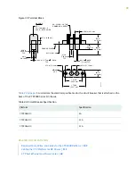
Страница 76: ...000 Platform 109 Cabling the CTP Platform for DC Power 111 Terminal Block and Circuit Breaker Specifications 69 Terminal Block and Circuit Breaker Specifications Table 23 on page 69 lists the electrical specifications for the terminal block see Figure 35 on page 70 located on the back of the CTP2000 Series DC chassis Table 23 Terminal Block Electrical Specifications Specification Category 100 VDC ...

Страница 77: ... 004 in TYP 27 in 6 86 mm MARKING 1 738 in 44 17 mm 1 312 in 33 35 mm 031 in 002 in 79 mm TYP Table 24 on page 70 summarizes the electrical specification for the circuit breaker that is attached on the back of the CTP2000 Series DC chassis Table 24 Circuit Breaker Specification Specification Platform 8 A CTP2008 DC 15 A CTP2024 DC 15 A CTP2056 DC RELATED DOCUMENTATION Required Tools Wires and Cabl...

Страница 78: ...3 PART Safety General Safety Guidelines and Warnings 72 Module Installation Safety Guidelines and Warnings 74 Hardware Compliance 76 ...

Страница 79: ...tall equipment in the rack from the bottom upward Doing this helps maintain the stability of the rack and reduces the chance of the rack tipping over WARNING Do not insert any metal object such as a screwdriver into an open slot or the backplane Doing so can cause electric shock and serious burns WARNING For the larger CTP series devices three people are required to install the device in a rack tw...

Страница 80: ...on equipment that is connected to power lines Metal objects heat up when connected to power and ground and can cause serious burns or become welded to the terminals CAUTION Evaluate the overall loading of the branch circuit before you install any equipment into a rack RELATED DOCUMENTATION Federal Communications Commission FCC Statement 78 FCC Requirements for Consumer Products 78 Food and Drug Ad...

Страница 81: ...re attaching power cables WARNING Remove jewelry including rings necklaces and watches before working on equipment that is connected to power lines Metal objects heat up when connected to power and ground and can cause serious burns or become welded to the terminals WARNING Do not insert any metal object such as a screwdriver into an open slot or the midplane Doing so can cause electric shock and ...

Страница 82: ...y Items for Installing CTP150 Modules Federal Communications Commission FCC Statement 78 FCC Requirements for Consumer Products 78 Food and Drug Administration Center for Devices and Radiological Health 79 Compliance with Canadian Regulations 79 75 ...

Страница 83: ...8 FCC Requirements for Consumer Products 78 Food and Drug Administration Center for Devices and Radiological Health 79 Compliance with Canadian Regulations 79 Statements of Volatility for Juniper Network Devices 82 Declaration of Conformity for CTP2000 Platforms Figure 36 on page 77 shows the Declaration of Conformity for the CTP2000 platforms 76 ...

Страница 84: ...2000 Declaration of Conformity RELATED DOCUMENTATION CTP2008 Platform Specifications and Certification 33 CTP2024 Platform Specifications and Certification 35 CTP2056 Platform Specifications and Certification 38 77 ...

Страница 85: ...for Consumer Products 78 Food and Drug Administration Center for Devices and Radiological Health 79 Compliance with Canadian Regulations 79 FCC Requirements for Consumer Products This equipment complies with FCC rules Part 68 On the back side of this equipment is a label that contains among other information the FCC Registration Number and Ringer Equivalence Number REN for this equipment If reques...

Страница 86: ...ment complies with 21 CFR 1040 10 and 1040 11 for the safe use of lasers RELATED DOCUMENTATION Federal Communications Commission FCC Statement 78 FCC Requirements for Consumer Products 78 Compliance with Canadian Regulations 79 Compliance with Canadian Regulations IN THIS SECTION Industry Canada Notice 79 Canadian Department of Communications Explanatory Notes 81 Industry Canada Notice IN THIS SEC...

Страница 87: ...s an indication of the maximum number of terminals allowed to be connected to a telephone interface The termination on an interface may consist of any combination of devices subject only to the requirement that the sum of the Ringer Equivalence Numbers of all the devices does not exceed 5 Avis CS 03 d Industrie Canada L étiquette du ministère des Communications du Canada indique que l appareillage...

Страница 88: ...es of the local telecommunications company The equipment must also be installed using an acceptable method of connection In some cases the company s inside wiring associated with a single line individual service may be extended by means of a certified connector assembly telephone extension cord The customer should be aware that compliance with the above condition may not prevent degradation of ser...

Страница 89: ...sateurs devraient s assurer que les mises à la terre des lignes de distribution d électricité des lignes téléphoniques et de la tuyauterie métallique interne sont raccordées ensemble Cette mesure de sécurité est particulièrement importante en milieu rural Attention Les utilisateurs ne doivent pas procéder à ces raccordements eux mêmes mais doivent plutôt faire appel aux pouvoirs de réglementation ...

Страница 90: ...2300 C EX3300 EX3400 24P EX3400 24T EX3400 24T DC EX3400 48P EX3400 48T EX3400 48T AFI EX4200 EX4300 EX4300 48MP EX4500 EX4550 EX4600 EX8200 XRE200 External Routing Engine LN Series LN1000 CC MX Series M7i M7i Compact Forwarding Engine Board CFEB M40e and M10i M320 MX5 MX10 MX40 and MX80 MX104 MX204 MX240 MX480 and MX960 83 ...

Страница 91: ... QFX3008 I QFX3100 QFX3500 QFX3600 QFX5100 24Q QFX5100 48S QFX5100 48T QFX5110 32Q QFX5110 48S QFX5200 QFX5200 32C QFX10008 and QFX10016 SRX Series SRX100 SRX110 SRX210B SRX210H POE SRX210H P MGW SRX220 SRX240H SRX240H POE SRX300 SRX320 SRX340 and SRX345 SRX550 SRX650 84 ...

Страница 92: ... SRX1400 SRX1500 SRX3400 and SRX3600 SRX5400 SRX5600 and SRX5800 SRX MP 1SERIAL SSG 520M T Series RE A 2000 Route Engine 85 ...

Страница 93: ...ion Unpacking and Inspecting the CTP Platform 87 Installing the Chassis 90 Installing Modules 93 Installing and Removing SFPs in a CTP Module 102 Upgrading Components for Memory Upgrades 106 Cabling 108 Powering On 115 ...

Страница 94: ...vice be sure you have the following tools No 2 Phillips screwdriver Utility knife Mechanical lift or at least two people to assist in lifting RELATED DOCUMENTATION Unpacking the CTP Device 87 Inspecting Platform Components and Accessories 88 If You Detect or Suspect Damage 89 Contacting Juniper Networks 89 Unpacking the CTP Device Depending on the device it may be delivered boxed bolted and strapp...

Страница 95: ...ts to the device 4 To avoid scratching the device when removing it from the skid detach one of the L brackets from the skid by removing the three screws RELATED DOCUMENTATION Before You Unpack the CTP Platform 87 Inspecting Platform Components and Accessories 88 If You Detect or Suspect Damage 89 Contacting Juniper Networks 89 Inspecting Platform Components and Accessories After you remove the equ...

Страница 96: ...ack the CTP Platform 87 Unpacking the CTP Device 87 Inspecting Platform Components and Accessories 88 Contacting Juniper Networks 89 Contacting Juniper Networks Please contact Juniper Networks at 1 888 314 JTAC from the United States Canada or Mexico or 1 408 745 9500 from elsewhere or contact your sales representative if you have any questions or concerns See Contacting Customer Support on page 1...

Страница 97: ...kes into consideration future expansion Have the tools and accessories needed to complete the installation Read and understand the clearance requirements for the front and back of the chassis for cable routing and other unit access See CTP2000 Environmental Requirements on page 40 for more information Read and understand the clearance requirements for the top and bottom of the chassis to ensure ad...

Страница 98: ... make sure that persons handling the device wear an antistatic device RELATED DOCUMENTATION Before You Install the CTP2000 Platform 90 Installing the CTP2000 Platform in a Rack 92 Cabling the CTP2000 Platform Overview 108 Special Guidelines for Installing CTP2056 Chassis in a Rack Before installing the CTP2056 platform in a rack consider the following guidelines You can install up to four CTP2056 ...

Страница 99: ...n the right side lift the device into the rack 3 Position the device in its designated location in the equipment rack Make sure the holes of the mounting brackets align evenly with the holes of the equipment rack on both sides 4 Starting at the bottom of the device secure the device in the equipment rack by using the 10 32 x 3 8 Phillips screws Have a third person do this for the larger and heavie...

Страница 100: ...h Card 98 Installing a PMC on CTP2000 Platforms 99 CTP2000 Modules Installation Overview In CTP2000 platforms you can install interface modules in the front and rear of the device RELATED DOCUMENTATION Protecting CTP2000 Modules and Slots 94 Required Tools and Safety Items for Installing CTP Modules 95 Safety Guidelines and Warnings for Installing CTP Modules 74 Installing a CTP Interface Module P...

Страница 101: ... action helps to protect the module from damage by electrostatic discharge CAUTION Always handle a module by its edges Do not touch the components pins leads or solder connections CAUTION If you meet strong resistance when attempting to seat a module using the ejectors remove it from the chassis and confirm that the slot is designed to hold the module Also be sure that you have aligned the left an...

Страница 102: ...ther device and connect it to one of the ESD grounding jacks if available or another grounding device 2 Choose the slot where you want to insert the module 3 With a Phillips screwdriver loosen the screws that secure the blank filler panel covering the empty chassis slot if present and remove the filler panel 4 Remove the module from its antistatic bag being careful not to touch module components p...

Страница 103: ...illips screwdriver NOTE Tighten the captive screws completely before installing an adjacent module so that proper electromagnetic interference EMI gasket compression occurs Failure to do this can make it difficult to install adjacent modules 9 Go to Cabling the CTP2000 Platform Overview on page 108 RELATED DOCUMENTATION Removing a CTP Interface Module Processor Module or Clock Module 96 CTP2000 T1...

Страница 104: ...d release buttons and pull the ejector handles outward to the open position 5 Carefully slide the module out of the chassis 6 Place the module in its antistatic bag being careful not to touch module components pins leads or solder connections 7 Cover the empty chassis slot with a blank filler panel and tighten the filler panel s captive screws using a Phillips screwdriver Turn both screws several ...

Страница 105: ...e processor rear transition module RTM Some CTP devices may ship with a CompactFlash card already installed To remove or install the CompactFlash card for the CTP2000 series with the new PP833 processor see Figure 37 on page 98 1 Power off the unit 2 If installed remove the PP833 PMC card by unscrewing the retaining screws and pushing the extractors outward with the latching buttons depressed 3 Yo...

Страница 106: ... the flash socket see Figure 38 on page 99 4 Reinstall the CompactFlash card retaining screw and nut 5 Reinstall the processor RTM into the chassis and secure the retaining screws Figure 38 CompactFlash on the RTM IIIIIIIIIIIIIIIIIIIIIIIIIIIII CompactFlash card CompactFlash locking screw g015386 RELATED DOCUMENTATION Installing a CTP Interface Module Processor Module or Clock Module 95 Installing ...

Страница 107: ...o of the screws are secured to standoffs and two are attached to the front assembly of the PMC Remove the two screws secured to the standoff leaving the standoff attached to the PMC Remove the two screws on the front assembly located on the side with the standoffs The front assembly should remain attached to the PMC hardware Keep the screws for reattachment 5 Align the PMC with the printed circuit...

Страница 108: ...ur Phillips head screws to secure the two PMC standoff posts and PMC front assembly to the processor module 8 Reinstall the processor RELATED DOCUMENTATION Installing a CTP Interface Module Processor Module or Clock Module 95 CTP2000 PMC Module 30 101 ...

Страница 109: ...Ps on interface modules that support these devices In the current release the CTP FX2000GE UPG supports SFPs You can replace the SFPs without disabling the interfaces or removing the module from the device To install SFPs 1 Ground yourself by using an antistatic wrist strap or other device and connect it to an ESD grounding jack 2 Identify the following items on the SFP Figure 40 on page 103 The c...

Страница 110: ...nstall the SFP 4 Slide the SFP as far as you can into the module until the SFP clicks into place If the SFP does not slide smoothly into the module make sure that the orientation of the SFP is correct 5 Gently pull the SFP to confirm that it is inserted correctly If the SFP comes out of the slot when you pull it repeat Step 4 6 Connect the new cables to the SFP RELATED DOCUMENTATION Removing SFPs ...

Страница 111: ...wrist strap or other device and connect it to an ESD grounding jack 3 Disconnect the cable from the SFP on the module 4 Identify the release mechanism for the SFP Different SFPs use different release mechanisms See Figure 41 on page 104 for possible release mechanisms which include A button that you press inward A ring that you press inward A bar that you pull sideways then outward A tab that you ...

Страница 112: ...Installing SFPs in a CTP2000 Module 102 105 ...

Страница 113: ...using an antistatic wrist strap or other device and connect it to one of the ESD grounding jacks if available or another grounding device 2 Choose the slot where you want to insert the module 3 With a Phillips screwdriver loosen the screws that secure the blank filler panel covering the empty chassis slot if present and remove the filler panel 4 Remove the module from its antistatic bag being care...

Страница 114: ...e module The small red release buttons should click into place 8 Tighten the module s captive screws using a Phillips screwdriver NOTE Tighten the captive screws completely before installing an adjacent module so that proper electromagnetic interference EMI gasket compression occurs Failure to do this can make it difficult to install adjacent modules 9 Go to Cabling the CTP2000 Platform Overview o...

Страница 115: ...ourself with the module ports and ensure that you have the cables and wires needed to complete each cabling procedure 2 Read and understand all safety warnings See CTP Safety Guidelines and Warnings on page 72 3 Connect timing ports 4 Connect grounding wires to the chassis 5 Connect the power cables from the power source to the power supply 6 Connect the interface modules to their appropriate netw...

Страница 116: ... applicable Two 10 kep nuts supplied to connect the ground earth wire to the ground terminal Power module wiring We recommend a minimum of 18 AWG wire for the device with a dual stud terminal lug with 5 8 inch spacing Consider the distance from the connection point and the configuration of the device when determining the size of wire used Table 25 Required Cables Port and Cable Used Connection One...

Страница 117: ...450 071855 the available RJ 45 console pinout will be similar to the CTP150 console port and other Juniper routers To connect the PP833 processor with the DB 9 male serial port of a PC additionally connect a straight RJ 45 cable with the DB 9 adapter from the bag labelled p n 720 056657 The other end of the RJ 45 cable connects to the DB 9 adapter from the bag labelled p n 720 014126 Then you can ...

Страница 118: ...ctor refer T1 E1 Interface Module Pinouts on page 51 RELATED DOCUMENTATION Required Tools Wires and Cables for the CTP2000 Platform 109 CTP2000 Management Ports 110 CTP2000 T1 E1 Interface Module 13 Cabling the CTP Platform for DC Power After you have correctly cabled the RTM for the CTP2000 Series you must attach grounding and electrical wires before you turn the device on Three main tasks are in...

Страница 119: ...atform Only 112 3 Task 3 Connecting the Power Cables to the CTP2000 Platform 113 Task 1 Turning Off All CTP Platform Power Push all device power switches to OFF to turn off the device Task 2 Connecting the Grounding Cable to the CTP Platform CTP2056 Platform Only The CTP2056 device has a grounding stud located in the rear of the chassis near the power inputs To ground the power unit 1 Locate the g...

Страница 120: ... color code of the power cables depends on the color coding of the DC power source installed at your site Color code standards for DC wiring do not exist To ensure that the correct polarity is connected to the device power units confirm the connection of the power cables to the positive and negative leads at the power source 2 Remove the nuts and locking washers from the posts for the power input ...

Страница 121: ...ads 8 Repeat Steps 1 7 for each power supply module in your configuration RELATED DOCUMENTATION CTP2000 Management Ports 110 Cabling a CTP2000 T1 E1 Interface Module 111 Required Tools Wires and Cables for the CTP2000 Platform 109 Terminal Block and Circuit Breaker Specifications 69 114 ...

Страница 122: ...ns for information about these tasks WARNING Be sure the power source is turned off and the device is turned off before you perform the installation tasks Installing a CTP Interface Module Processor Module or Clock Module on page 95 Cabling a CTP2000 T1 E1 Interface Module on page 111 Cabling the CTP Platform for DC Power on page 111 Setting Up Management Access on the CTP2000 Platform on page 121...

Страница 123: ...vice 1 Verify that the power source is operational 2 Inspect all grounding and power connections to the device chassis 3 Confirm that all cable connections are secure 4 Switch any available power switches to ON 5 Monitor LEDs to verify that the device is booting properly The device goes through a boot process When a prompt appears on the system console the device is ready to be configured If the s...

Страница 124: ... bytes as the default 9 Static routes added to the default interface if any 10 Date and time GMT more precisely UTC Enter these separately in digits for the month day hour and minutes in Coordinated Universal Time UTC or accept the internal settings The device goes into startup mode For example Setting up the root password Changing root s password Changing password for user root New password Retyp...

Страница 125: ...onfiguration for eth1 default device Please input the ip return for 127 0 0 1 172 25 61 54 Please input the netmask return for 255 255 255 0 255 255 255 128 Please input the gateway return for 127 0 0 1 172 25 61 1 Please input the mtu in bytes return for 1500 Add route to interface eth1 n OS Security level set to LOW Setting up date time Setting the date GMT Please input the year 2008 2020 return...

Страница 126: ...se the LEDs on each module to determine the status of the device Observe the module LEDs on the front or rear components RELATED DOCUMENTATION Before You Power On the CTP2000 Platform 115 Powering Off the CTP Platform 119 Powering Off the CTP Platform se to power device 1 From the Main Menu select 5 Node Operations 2 From the Node Operations Menu select 10 Powerdown Node 119 ...

Страница 127: ...5 PART Configuration Accessing the CTP2000 Platform 121 ...

Страница 128: ...nicate with the device you must have a terminal emulation program running on your PC or Macintosh You can use any terminal emulation program such as HyperTerminal A UNIX workstation can use the emulator TIP You can connect a local serial console to the COM2 port on the PP310 and PP332 processors On the PP833 processor a local serial console is connected using the supplied USB to DB9 cable p n 720 ...

Страница 129: ... PC Macintosh or UNIX workstation directly to the CONSOLE terminal port When you connect a local serial console directly to the device you can configure the device without an IP address To communicate with the device you must have a terminal emulation program running on your PC or Macintosh You can use any terminal emulation program such as HyperTerminal A UNIX workstation can use the emulator TIP...

Страница 130: ...latform If your console uses a version of Microsoft Windows such as Windows XP or Windows NT 4 0 that supports the HyperTerminal application you can access the device through HyperTerminal 1 Click the Start button and select Programs Accessories Communications and HyperTerminal 2 In the HyperTerminal window select HyperTerminal 3 In the Connection Description dialog box enter a name for your devic...

Страница 131: ...rt enables you to monitor the device while it boots To connect a console directly to the device 1 Connect the female DB 9 connector to the COM 2 port on the device s RTM 2 Connect the crossover adapter connector to your PC s serial port 3 Power on the device When you power on the device the CLI appears on your console s screen You can begin configuration RELATED DOCUMENTATION Setting Up Management...

Страница 132: ...DC power versions of the platform 2 Connect the other end of the cable to the appropriate Ethernet network for an out of band connection CAUTION Do not change the IP address for the Ethernet interface that you are using to communicate with the device If you change the address you will lose the SSH session RELATED DOCUMENTATION Setting Up Management Access on the CTP2000 Platform 121 CTP2000 Consol...

Страница 133: ...6 PART Maintenance Maintaining Components 127 Product Reclamation and Recycling 131 Replacing Fan Trays 133 Packing and Returning Hardware 135 ...

Страница 134: ...ntistatic wrist strap Antistatic bags or other protective packaging to hold components Plastic boots or other protective covers for fiber optic connectors RELATED DOCUMENTATION Storing CTP Modules and Other Components Cleaning the CTP Platform 128 Storing CTP Modules and Other Components Retain the packaging in which a module or other component was shipped and use this packaging to store the item ...

Страница 135: ...r Maintaining the CTP Platform 127 Cleaning the CTP Platform 128 Cleaning the CTP Platform Dust is attracted to the area where the air intake vents are located Clean the area with a dry cloth every few weeks to prevent excessive accumulation of dust This cleaning helps to maintain the efficiency of the cooling system and to prevent damage to electronic components WARNING Do not insert any metal ob...

Страница 136: ...ast 60 seconds before turning it back on To remove an AC power supply see Figure 42 on page 130 for a representative AC power supply at the rear of the chassis 1 Switch off the dedicated customer site circuit breaker for the power supply and remove the power cord from the AC power source Follow the instructions for your site 2 Attach an electrostatic discharge ESD grounding strap to your bare wris...

Страница 137: ...alled in the power supply slot 3 Tighten both captive screws at the bottom of the power supply 4 Attach the power cord to the power supply 5 Attach the power cord to the AC power source and switch on the dedicated customer site circuit breaker Follow the instructions for your site 6 If the chassis has a power switch move it to the on position 7 Observe the status LEDs on the power supply faceplate...

Страница 138: ... mechanisms for the recycling and reuse of their products The RoHS Directive restricts the use of certain substances that are commonly found in electronic products today Restricted substances include heavy metals including lead and polybrominated materials The RoHS Directive with some exemptions applies to all electrical and electronic equipment In accordance with Article 11 2 of Directive 2002 96...

Страница 139: ...d recovered or disposed of in a responsible manner Our packaging is designed to be recycled and should be handled in accordance with your local recycling policies RELATED DOCUMENTATION Return Procedure 135 Returning CTP Products for Repair or Replacement 136 132 ...

Страница 140: ...ngers near the fans when removing the fan tray The blades might still be moving 2 Gently pull the fan tray out Place one hand under the fan tray and the other on the front handle and continue to pull it out of the chassis Use two hands to hold the fan tray after it comes out of the chassis RELATED DOCUMENTATION Installing a CTP2000 Fan Tray 133 Installing a CTP2000 Fan Tray To install the fan tray...

Страница 141: ...cal connector on the back of the fan tray pairs with an electrical connector at the back of the shelf 3 With an appropriate screwdriver tighten the captive screws Alternate between screws when tightening them to ensure that the electrical connectors at the back of the tray fit tightly RELATED DOCUMENTATION Removing a CTP2000 Fan Tray 133 134 ...

Страница 142: ...AC on page 141 Provide the following information in your e mail message or during the telephone call Part number and serial number of component Your name organization name telephone number and fax number The shipping address for the replacement component including contact name and phone number Description of the failure The support representative validates your request and issues an RMA number for...

Страница 143: ...tive for information about approved packaging material See the customer support Web page for complete repair and return policies and procedures To pack the chassis for shipment 1 Ground yourself by using an antistatic wrist strap or other device 2 Issue the proper shutdown commands to halt your system 3 Switch all power switches to the OFF position 4 Remove all cables from the chassis 5 Remove all...

Страница 144: ...7 PART Troubleshooting Troubleshooting Power Failures 138 Contacting Customer Support 140 ...

Страница 145: ...s malfunctioned Power source cannot handle system load Solution 1 Verify that all power connections are correct 2 Verify that the power supply is delivering the correct voltage current and wattage to the device See the system specifications for your particular CTP Series platform 3 If the platform still does not operate contact the Juniper Networks Technical Assistance Center JTAC RELATED DOCUMENT...

Страница 146: ...ost Solution 1 Verify that power connections are properly attached 2 Verify that device is receiving power 3 Look to see whether or not the LEDs are lit 4 Run diagnostics using the CLI 5 If the device does not reset contact JTAC RELATED DOCUMENTATION CTP Platform Does Not Power On 138 139 ...

Страница 147: ...enience we provide multiple options for requesting and receiving technical support from the Juniper Networks Technical Assistance Center JTAC By the Web using Juniper Networks Inc Service Request Manager https support juniper net support By telephone From the US Canada and Mexico at 1 888 314 JTAC From all other locations at 408 745 9500 RELATED DOCUMENTATION Return Procedure 135 Locating CTP Comp...

Страница 148: ...ting technical support from JTAC by phone be prepared to provide the following information Priority level Indication of what activity was being performed on the device when the problem occurred Problem detail and configuration data When a new request for technical support is submitted the JTAC engineer 1 Opens a case and assigns a number 2 Begins troubleshooting diagnostics and problem replication...

Страница 149: ...Locating CTP Component Serial Numbers 141 Returning CTP Products for Repair or Replacement 136 142 ...

Отзывы: