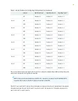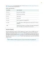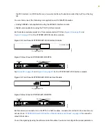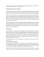
to the B bit. Because the signaling is bidirectional, the FXS side must echo the B bit when sending out the
A bit.
The same logic applies to the FXO interface. The FXO device goes on/off-hook. It must respond to the A
bit, going off-hook when A transitions from 0 to 1, and going on-hook when A goes from 1 to 0. The analog
FXO interface detects ringing; therefore, it is responsible for generating the B bit value. The FXO device
must echo the A value when sending out the digital signaling over the network.
Two situations for this call sequence must be considered: when the CTP is the FXO device and when the
CTP platform is the FXS device. In both cases, before the call starts, the FXO is on-hook (A=1) and there
is no ringing (B=1).
•
For an analog CTP FXS interface, before the call starts, the CTP interface must generate A=0 and send
both A=0 and B=1. When the call initiates from the CO, the B bit is toggled. In response to this toggling,
the CTP device generates a ring voltage on the analog FXS interface. When the attached FXO device
goes off-hook, the CTP FXS interface detects the off-hook, sets the A bit to 1, and stops the ring voltage.
During the call, the CTP device sends A = B = 1 signaling bits. At the end of the call, the FXO device
goes back to on-hook, the CTP detects the on-hook, sends out A=0 and B=1 signaling bits, and the circuit
returns to the idle state.
•
For an analog CTP FXO interface, before the call starts the FXO is on-hook and no ringing is generated
by the attached FXS device. In this, the idle state, the CTP interface generates B=1 and sends both A=0
and B=1. When the call comes in from the CO, the CTP FXO interface detects ring voltage and starts
toggling the B bit. When the other end of the VCOMP bundle goes off-hook, it sends A=1 to the CTP.
In response, the CTP FXO interface closes the loop, going off-hook. With ringing stopped, the CTP
interface sends A = B = 1 during the call. At the end of the call the interface is again idle, and the CTP
interface sends A=0 and B=1 signaling bits.
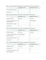
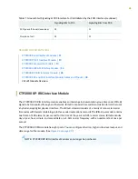
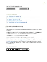
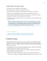
Digital FXS/FXO Ground-Start Signaling
Unlike loop-start interfaces, in which the FXO and FXS each separately control a single signaling bit, with
ground-start signaling each side controls both the A and B bits. We must consider each interface when
the call is initiated by either interface. (See
,
and
). In all cases, when the FXO/FXS interface is idle, the FXO interface generates A
= B = 1 signaling bits and the FXS A = 0, B = 1. When a call is in progress, either side initiates a call
termination if it receives these signaling bits. For example, an FXS goes on-hook if it receives A=B=1
signaling bits.
Table 4: Ground-Start Signaling at FXO Interface for Call Initiated by the FXO Interface
Signaling Bits from FXO
Signaling Bits to FXO
11 (A=1, B=1)
01 (A=0, B=1)
Idle (before call starts)
11
00
FXO grounds ring
01
00
FXS goes off-hook (grounds tip)
24
Содержание CTP2000 Series
Страница 1: ...CTP2000 Series Circuit to Packet Platforms Hardware Guide Published 2020 08 31 ...
Страница 8: ...1 PART Overview CTP2000 Series Platform Overview 2 CTP2000 Series Interface Modules 11 ...
Страница 112: ...Installing SFPs in a CTP2000 Module 102 105 ...
Страница 127: ...5 PART Configuration Accessing the CTP2000 Platform 121 ...
Страница 144: ...7 PART Troubleshooting Troubleshooting Power Failures 138 Contacting Customer Support 140 ...
Страница 149: ...Locating CTP Component Serial Numbers 141 Returning CTP Products for Repair or Replacement 136 142 ...


