


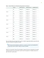


See
for signal definitions. See
“CTP2000 4WE&M Interface Connector Pinouts” on
for the connector A and B pinouts.
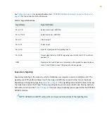
Table 2: Signal Definitions
Signal Definition
Signal Name
Audio transmit pair, 600 Ohm
Port x T, R
Audio receive pair, 600 Ohm
Port x T1, R1
E lead–output
Port x E
M lead–input
Port x M
Input for signal ground for signaling type II
Port x SG
Output signal battery (–48V) for signaling type II. Note that JP17 must be in
position 1-2.
Port x SB
Signal ground. E and M leads are referenced to this ground for signaling types
I and V. Use JP26 to connect this ground to chassis ground.
GND
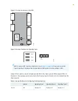
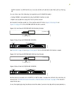
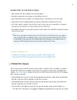
Supervisory Signaling
Supervisory signaling is the means by which a telephone user requests a service or initiates a call. The
signaling unit (CTP platform) interacts with the trunk unit (PBX) by means of either two or four leads,
depending on the signaling type. (See
.) The signaling unit controls the E lead, whereas
the trunk side controls the M lead. The two signaling states are on-hook and off-hook. During inactivity
both units are on-hook. See
for a summary of signaling types supported by the CTP2000
4WE&M module.
NOTE:
4WE&M and 4WTO audio paths are always up independent of the signaling state.
18
Содержание CTP2000 Series
Страница 1: ...CTP2000 Series Circuit to Packet Platforms Hardware Guide Published 2020 08 31 ...
Страница 8: ...1 PART Overview CTP2000 Series Platform Overview 2 CTP2000 Series Interface Modules 11 ...
Страница 112: ...Installing SFPs in a CTP2000 Module 102 105 ...
Страница 127: ...5 PART Configuration Accessing the CTP2000 Platform 121 ...
Страница 144: ...7 PART Troubleshooting Troubleshooting Power Failures 138 Contacting Customer Support 140 ...
Страница 149: ...Locating CTP Component Serial Numbers 141 Returning CTP Products for Repair or Replacement 136 142 ...