4
Information
Please note that you can find the pictures and illustrations
we are referring to on page 5.
Warning
·
Unless directions are followed and original spare parts
used, physical injury or property damage may result.
·
Protect compressor against rain, moisture, frost and dust.
·
Compressor is only suitable for installations with the nomi
nal voltage stated on the motor plate.
·
The compressor is constructed and approved for a max.
pressure of 10 bar/150 psi. Do not adjust the compressor to
a higher pressure.
·
Do not in any way block or prevent the normal functioning of
the safety valve on the receiver.
·
Only connect pneumatic equipment suitable for the max.
pressure indicated.
·
Do not operate compressor at ambient temperatures
exceeding 5°C/95°F or falling below 0°C/2°F.
·
Do not touch compressor motor during operation as there is
a risk of burn due to high temperatures.
·
Do not direct air flow at head or body.
·
When a flammable liquid is sprayed, there may be danger of
fire or explosion, especially in closed rooms.
·
Defectuous inlet cable on x400V units must be replaced
by authorized personnel from JUNAIR International A/S or
skilled craftsmen.
·
Always keep the compressor out of reach of children.
Note!
This product must be connected to a power supply
branch protected by a fuse or circuit breaker with a
rating of not less than 20 A, in order to comply with
the essential requirements of the EMC-directive 89/
336/EEC of may 3rd. 1989.
Guarantee
Provided that the operational instructions have been carried out,
your JUNAIR compressor is guaranteed against faulty material
or workmanship for 2 years.
The air receiver is guaranteed for 5 years.
The guarantee does not cover damage caused by violence,
misuse, incorrect repairs or use of unoriginal spare parts.
Costs of transportation of parts/equipment are not covered by
the guarantee.
JUNAIR’s Conditions for Sale and Delivery will generally apply.
JUNAIR International A/S reserves the right to change
technical specifications/ constructions.
How to operate the JUN-AIR compressor
Your JUNAIR compressor is very easy to operate. Observe
the following simple instructions and you will get many years’
service from your compressor.
1. Visually inspect unit for shipping damage, contact your
supplier immediately if you think the unit may have been
damaged.
2. Place the compressor in a dustfree, dry and cool, yet
frostfree, room. Do not install in a closed cupboard, unless
adequate openings for ventilation are available on top and
bottom (minimum 500 cm²/77.5 in² each). If the compressor
is placed under a table, a minimum of 20 cm/7.9 in free
height must be available above the compressor, or an
opening of Ø0 cm/11.8 in, corresponding to the fan
opening at the upper part of the compressor cabinet or
above the cylinder head of the compressor, should be cut in
the table.
. The four rubber legs are adjustable to ensure that the
compressor stands firmly on the floor (fig. 1).
4. The pneumatic equipment is connected to the pressure
regulator either by using the hose tail and securing with a
hose clamp, or by unscrewing the hose tail and utilizing the
1/4" BSP thread for other preferred connections (fig. 2).
5. Hoses from filter, dryer and autodrain must be led to a
drain or container, e.g. JUNAIR bottle for condensate
(standard on model BDPD) (fig. ).
6. Connection 20V:
Plug the compressor into an outlet switch of nominal voltage
and ensure that fusing is adequate (see technical details).
7. Connection x400V:
Plug the compressor into an ordinary x400V mains switch
with grounding and ensure that fusing is adequate (see
technical details). If the compressor does not start, the
phase sequence in the plug is incorrect, and the two phases
in the plug have to be changed. (The wires in the terminal
box and the motor protection are not to be touched).
Installations for x400V are fitted with phase sequence
relay as the compressor must not rotate in the wrong
direction.
8. Start the compressor using the 0/1 switch on the pressure
switch (fig. 7). The compressor will automatically switch off
at the preset pressure. If the motor does not start it may
be due to pressure in the receiver, and the motor will then
start automatically when the pressure reduces to approx.
6 bar/87 psi. If the compressor is fitted with a cabinet,
the ventilation starts automatically at an internal cabinet
temperature of 6°C/97°F.
9. To obtain a constant output pressure, adjust the regulator
at the desired pressure. The regulator can be locked by
pushing down the regulating knob.
10. Adjustment of pressure (fig. 4):
A:
Max. pressure adjustment (cutout)
B:
Differential adjustment (cutin)
The cutin pressure (normally 6 bar) is set by adjustment
of differential screw B. Turn clockwise to reduce cutin
pressure.
The cutout pressure is set by even adjustment of the two
screws A. (Cutin pr differential = cutout pressure).
Turn clockwise to increase cutout pressure.
The switch is normally factory set for operation at 68 bar
(approx. 90120 psi).
Technical details
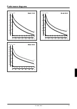
For tables with technical data and performance curves, see
page 14.
Operating manual
Operating manual
GB
Содержание 1000 motor
Страница 2: ......
Страница 11: ...11 10 4 A B 6 B A 6 8 90 120 psi 50 15 8 120 psi 15 14 2 30 psi 32 89 F BD PD 2000 RU...
Страница 20: ...20 Motor spare parts model 1000 0100400 Spare parts...
Страница 21: ...21 Motor spare parts model 2000 0200300 Spare parts...
Страница 22: ...22 0200600 Spare parts model 2000 40B Spare parts...
Страница 23: ...23 Spare parts model 2000 40BD2 0200610 Spare parts...
Страница 24: ...24 0200620 Spare parts model 2000 40P Spare parts...
Страница 25: ...25 0200630 Spare parts model 2000 40PD2 Spare parts...
Страница 26: ...26 Spare parts model 4000 40B 0400200 Spare parts...
Страница 27: ...27 Spare parts model 4000 40BD3 0400210 Spare parts...


