background image


- 24 - 

Note: 

when  powered  on,  it  is  a  little  warm  during  working  on  the  positions  of  the 

module of low noise amplifier in the middle of image transmission extension cord, if the 

module  isn't  warm,  please  test  the  line  connection  and  contact  with  the  after-

salepersonnel...   


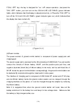
Figure 3.2.2


(3) Clockwise connect the two image-transmission antenna extension cords of ground 

control station to the SMA female's fastener of antenna base, which is as shown as 

Figure 3.2.3. 


Figure 3.2.3


Image 
transmis
sion 
antenna 

Data 
transmissi
on 
antenna


Connec

tor 

Содержание T60 V1

Страница 1: ...1...

Страница 2: ...ON 18 3 1 COMPOSITION OF GROUND CONTROL SYSTEM 18 3 2 OPERATIONS OF GROUND CONTROL STATION 23 3 3 SOFTWARE OPERATION 27 3 3 1 Connection 27 3 3 2 Main interface 28 3 3 3 Quick Access Toolbar 31 3 3 4...

Страница 3: ...3 17 fault protection 55 3 3 18 Geographical rail 56 4 INSTRUCTIONS FOR FLYING 57 4 1 CHECK UP BEFORE FLYING 57 4 2 AIRCRAFT CALIBRATION 57 4 3 ANALYSIS AND ANSWERS TO FAQ 60 4 4 WARRANTY INFORMATION...

Страница 4: ...is recommended that the aircraft flies in a special flight site Do not operate the aircraft when you are tipsy fatigue or in poor mental state please operate in strict compliance with the user manual...

Страница 5: ...roduct the user shall be liable for any violation of public order or public safety 3 We do not provide any technical support and security commitments under the following situations 1 The unit or indiv...

Страница 6: ...st 1 T60 airframe 1 T60 arm 6 T60 airframe including flight control system image transmission system digital transmission system and electronic system T60 arm including motor electronic speed controll...

Страница 7: ...connection of aircraft Step 1 open the packaging aluminum case of aircraft and take out the relevant components of aircraft for further installation Step 2 take out two T shape stands from the aircra...

Страница 8: ...Step 4 have the supportive data transmission image transmission antenna of aircraft installed according to the corresponding locations Step 5 instructions for installation of payload equipment Take o...

Страница 9: ...Step 1 take out the power battery of ground control station UAV unmanned aerial vehicle Step 2 after you have completed the wiring as follows the power supply unit is connected to the AC at 220V and...

Страница 10: ...ed first press the STOP START 1 or STOP START 2 button and rotate the round button in the middle Select the battery option of 0 LiPo and confirm the setting by pressing the round button in the middle...

Страница 11: ...ght side Set the LiPo Cap as Ignore and Cells as 22 2V 6S and Current as 15A and Chg Mode as Normal Balance Figure 1 3 3 Step 5 rotate the cursor to Start and click rotary switch to confirm and you ju...

Страница 12: ...charged and you just need to disconnect the power supply as shown in Figure 1 3 2 Figure 1 3 5 1 4 Description and use of the remote control Serial no Name of switch Function Description 1 LDrotary s...

Страница 13: ...d s tilting adjustable Gear 2 of SC controls the tilting of cradle head and the rolls of LD and RD switch adjustable Gear 3 of SC controls the LD and RD switches of tapered end mode of control cradle...

Страница 14: ...sufficient In case of low battery charge the remote battery in time 3 Arm flight when the aircraft and the ground control station are normally powered on the aircraft is connected through the ground...

Страница 15: ...mode the RTL and LAND state can be realized only with reliable GPS signal When the current height of aircraft is lower than 15 meters the aircraft will make a return voyage and land on the take off p...

Страница 16: ...Note in the mode after the air route is successfully set there is no need to connect the aircraft through the ground control station and the aircraft will cruise based on the set air route In this mod...

Страница 17: ...nstantly glows GPS locked unlocked The green indicator constantly glows GPS mode air route mode unlocked unlocked The green indicator constantly glows GPS mode air route mode locked Armed The green in...

Страница 18: ...lasts for 3 seconds The calibration is successful The green indicator flashes twice every second which lasts for 5 seconds The calibration fails The red indicator flashes twice every second which las...

Страница 19: ...the next level in the standby mode click MENU button and it will pop up the menu option and you can enter the menu to set parameters After entering the detailed project conditions MENU enables the ret...

Страница 20: ...f lithium battery XH 6P and the positive pole red line and negative electrode black line of lithium battery to the male red line and black line of XH 6P inside the ground control station corresponding...

Страница 21: ...station and select control panel and enter the interface of adjust the settings of the computer click to enter view network status and tasks and select change the adapter settings and enter Local Con...

Страница 22: ...ut to other display equipment through the external HDMI extension cord e video recording interface The USB interface of video recording output of ground control station can be connected to the mobile...

Страница 23: ...shown in Figure 1 3 2 Figure 3 2 1 Step 2 installation of data transmission image transmission feeder line 1 clockwise rotate and push the supportive data transmission antenna of ground control statio...

Страница 24: ...if the module isn t warm please test the line connection and contact with the after salepersonnel Figure 3 2 2 3 Clockwise connect the two image transmission antenna extension cords of ground control...

Страница 25: ...t order and use the Velcro strips to tighten them Then connect the black line XT150 connector and the red line AS150 connector with the input power of ground control station successively before poweri...

Страница 26: ...click the power supply metal switch on the panel and the blue indicator of metal switch is lighted and then the equipment is started It is shown as Figure 3 2 6 Figure 3 2 6 Step 5 shutdown of ground...

Страница 27: ...n for power supply on the panel to disconnect the power supply of ground control station and the operation is shown as Figure 3 2 8 Figure 3 2 8 2 Based on the actual situation check whether the batte...

Страница 28: ...hing and normal positioning UAV will send GPS data and feedbacks to the ground control station and the ground control station will plot out the UAV s locations and head s directions on the map 1 The i...

Страница 29: ...ion signal when the data transmission signal is in good status it is green when the flying instructions for GUIDED are poorly received if the data transmission is poor it will prop up the dialog box i...

Страница 30: ...Display of system time 10 Shortcut menu column immediately switch to the real time cruise GUIDED planning parameter setting interface capable of immediately implementation of functions such as RTL LAN...

Страница 31: ...rch function search for the location that has been marked and you can locate the corresponding marked points by entering the keyword pressing Enter or clicking the search icon The search supports the...

Страница 32: ...route after UAV takes off you can mark the real time GUIDED line on the map and this GUIDED line can be applied to the function of flying by GUIDED 10 Map tools supports the toggling among three maps...

Страница 33: ...33 Instrument board interface...

Страница 34: ...sArm status of UAV 11 GPS status 12 Message box display the prompt of battery alarm and rail overstepping and so on 13 Display mode and status 14 Displays the number of target GUIDED and the distance...

Страница 35: ...UAV and it will be locked if there is no operation DisArm you need to lock the UAV when the UAV is unlocked or under emergencies on the ground Click the Arm DisArm button on the instrument board and t...

Страница 36: ...t is more than 5 meters and lower than 15 meters the height within 5 meters is considered as the ground it can t switch to the GUIDED cruise if the height is lower than 15 meters 15 seconds after unlo...

Страница 37: ...n the Quick Access Toolbar 2 On the instrument board 3 3 7 Guided flight Guide the UAV to the designated point and double click the map to realize the designated point flight in the GUIDED cruise and...

Страница 38: ...oad to the UAV and the ground control station will distribute the GUIDED to UAV in turn based on the UAV cruise situation 2 In the process of GUIDED cruise you can drag and delete other GUIDED in real...

Страница 39: ...nter the mode of configuration of GUIDED point operation and the UAV mode will switch to GPS 2 3 Configuration of real time GUIDED point Click GUIDED point configuration in the map interface and the s...

Страница 40: ...icon cruise around the edited point on the shortcut icon area to determine the circle radius and number of circles 2 3 The system automatically generates a point of interest on the map 13 encircling G...

Страница 41: ...l time GUIDED point and the encircling real time GUIDED point can be set in alternative style 3 3 9 Automatic Cruise The automatic cruise refers that the planned GUIDED point information can be writte...

Страница 42: ...GUIDED planning without editing the air route status it will automatically load the automatic flight route stored in the flight control by switching to the interface the interface provides the plannin...

Страница 43: ...area that needs the download of offline maps 2 Click download map to download the offline map of the selected area you can also download the offline map of entire review area by clicking download map...

Страница 44: ...multiple choices are allowed press and hold the Ctrl key and drag and click the numbers of GUIDED point in the GUIDED list 7 Clear all GUIDED points clear all GUIDED points in the interface Command o...

Страница 45: ...cally repeat this task before the command Note 1 Only one command is supported after one marked point and if you cannot add a new command then mark another point 2 After the landing command and RTL co...

Страница 46: ...DED point to change with the left mouse button Drag anywhere on the map to change the positions of all selected GUIDED points and generate a new air route Enter the latitude and longitude to change th...

Страница 47: ...ED list and enter the new time values in the lingering m above the GUIDED list and click the change the height beside it to change the lingering time of single GUIDED point Change the lingering time o...

Страница 48: ...central point on the map interface of GUIDED planning and then click the button of cruise around GUIDED point to insert encircling GUIDED points and the GUIDED point is selected as the interest point...

Страница 49: ...reaches the height of 15 meters and when it implements the automatic cruise the GUIDED planning interface will automatically load the flight route note if UAV are flying in the sky UAV will cruise ac...

Страница 50: ...e and so on 3 3 10 Interest Point During flight the head of UAV will point to a location maredon the map here the functions of interest point on the instrument board is introduced and click the button...

Страница 51: ...interest point the head points to the interest point during flight if you cancel the interest point the head restore the original direction 2 If there is any interest point of encircling GUIDED points...

Страница 52: ...mum RTL height can be set in parameter setting geographical rail and now the mode is displayed as RTL 1 You can click status switch RTL to perform RTL 2 You can click RTL on the shortcut menu column t...

Страница 53: ...s of UAV and the mode is displayed as ALTHOLD You can click status switch ALTHOLD 3 3 15 Change the height and speed It changes the height and speed during the flight of UAV Input the height and speed...

Страница 54: ...l distance between current location of UAV and HOME point Total length of flight the total distance that UAV has finished and the time before the ground control station disconnected can be accumulated...

Страница 55: ...ent GPS satellites that UAV has searched GPS altitude current altitude height of GPS Height of home height of HOME point that GPS has measured 3 3 16 3 Data of input and output channels This interface...

Страница 56: ...continued in the modes of disable RTL LAND and AUTO mode 3 3 17 3 Data disconnect 5S triggering actions You can set that if UAV doesn t receive any actions that the signal of ground control station im...

Страница 57: ...rved paddle and the paddle of No 2 4 and 6 is positive paddle and finally make sure that the fixing airscrew is firmly fixed 3 Start the remote of UAV you need to start the remote before powering on y...

Страница 58: ...and forth the red blue and green indicator lights flash alternatively and enter the calibration mode After the indicator turns to blue and glows for 3 seconds you can rotate as shown by picture and yo...

Страница 59: ...bration interface or click parameter setting horizontal calibration on the shortcut menu column 2 The UAV unmanned aerial vehicle is placed at horizontal level and click the button of horizontal calib...

Страница 60: ...signal is extremely unstable Ask when you test the lost control protection on the ground you switch to the RTL LAND or shut down the control the motor will stop is the phenomenon normal Will the same...

Страница 61: ...61...

Отзывы: